This thread has been locked.

If you have a related question, please click the "Ask a related question" button in the top right corner. The newly created question will be automatically linked to this question.

Changing Output after few mins

Other Parts Discussed in Thread: INA101

Hi,

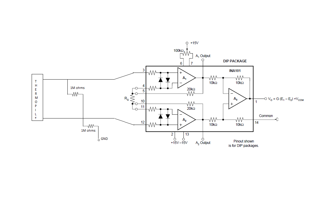
I'm using INA101 (DIP package)  for amplification of a 0-5 mV signal from a thermopile sensor. Power supply is at +/-12V, which is within the supply range mentioned in the datasheet. The circuit is made exactly as shown in the datasheet, with Rg = 40 ohms to set the gain=~1000. Offset is set to get an output voltage of 0.01V.

At first, everything works fine and my output voltage equals I/P x 1000. Few mins later, the set offset voltage suddenly increases to ~0.30V at the output (Input remains the same) and heating the thermopile sensor again will only give me an maximum output of ~1V, when I/P equals 5mV. I can't figure out the reason for what might be wrong. I have also failed to understand what rated output voltage means in the datasheet. Can the reason for the problem be the the failure of output to fall within the mentioned range?

Please help me with the same.

Regards,

Deep.

  • Hi Deep,

    can you show us a complete schematic?

    Which thermopile sensor do you use?

    Kai
  • Hi Kai,

    The therompile sensor used is a thin film type sensor. And below i have show the complete schematic of my circuit.

    Deep.

  • Hi Deep,

    this can be a normal output voltage variation of sensor during power-up. But unfortunately you didn't tell us the sensor type, so I cannot find out whether this is the issue.

    The INA101 has a rather high input bias current. This can be problematic if the sensor is high ohmic. But unfortunately you didn't tell us the sensor type, so I cannot find out whether this is the issue.

    Take care with the offset voltage adjust. Datasheet says, that only the input offset voltage of INA101 must be adjusted by the built-in offset voltage calibration scheme, but not the offsets of the source and system. So, to properly adjust the input offset voltage, short the input leads and adjust the output voltage of INA101 to 0V. Then, remove the short again.

    Kai
  • Deep

    We haven't heard back from you so we assume you were able to resolve your issue. If not, post another reply below.

    Thanks
    Dennis
  • Hi Dennis,

    I  don't know what the problem was, but disconnecting the external offset adjustment circuit (marked in red) at pin14 and grounding the pin solved the problem i was facing.

    I noticed another mistake i the pic i uploaded earlier. The resistor at pin12 to ground , required to provide path to the input bias current is kept 1M ohms and another 1M ohm resistor is connected between the input pins to decrease the input impedance to a value little less than 1M ohms. Below i have given the diagram of the working circuit.

    Thanks

    Deep

  • Deep

    Were glad you were able to resolve your issue.

    Thanks
    Dennis