Because of the holidays, TI E2E™ design support forum responses will be delayed from Dec. 25 through Jan. 2. Thank you for your patience.

This thread has been locked.

If you have a related question, please click the "Ask a related question" button in the top right corner. The newly created question will be automatically linked to this question.

DRV8711 randomly dies

Other Parts Discussed in Thread: DRV8711, CSD18531Q5A

Hey guys,

we have designed a step motor controller based on the TI DRV8711 and are testing our prototypes.
The last two days we are trying to tune the control parameters per SPI and we have more than three damaged DRV8711s.
More than three means: At least three died without any physical sign (when setting the enable pin or while running),
and one has literally  blown up while running.

I want to add that we're tuning the DRV8711s parameters, and tried extreme values to examine their impact, yet I would not
expect any MOSFET driver to die because of that?
(Still it seems, since we're driving the mosfets with less current: 200/150mA instead of 400/200 mA, the DRV8711 is less likely to die)

We supply the DRV8711 with 48V, you can find the schematic and datasheets for MOSFETS and motor attached.


Here is our most recent configuration of the DRV8711:

CTRL REGISTER:  0x0EA1  (1/32 Microstepping, Externall stall detect, Gain of 20, 850ns Dead Time

TORQUE REGISTER : 0x0050 (SMPLTH 50us, Torque 96)

OFF REGISTER: 0x0020 (use internal indexer, TOFF 32 x 500ns)

BLANK REGISTER: 0x0020 (disable adaptive blanking time, TBLANK 32 x 20ns)

DECAY REGISTER: 0x0032 (Tdecay 50 x 500ns, DECMOD: 000 in standstill and 100 when rotating)

STALL REGISTER:0x0C00 (we use external stall detection)

DRIVE REGISTER: 0x0941


Best regards from AUSTRIA,
Ioannis & Florian

EDIT 1:
> "MLeist" == GND_power

> attached datasheet of smd emi-suppression ferrit "WE-SUKW-7427512" of LCR filter

EDIT 2:

> attached layout of top layer

1565.Schematic.pdf

MOSFSET.pdf

motor-nanotec_ST5918S3008-A.PDF

we-skuw-7427512.pdf

Layout.pdf

  • Hi Ioannis,

    Thank you for the information.

    On your provided schematic, the net "MLeist" does not show a connection back to the main ground net. Is this present on another page in the schematic? Could you please provide it?

    In your LCR filters on page 8, what are the values of L6-L8?
  • Hi Phil,

    tnx for your fast answer!

    "MLeist" is GND_power. (german abbreviations here)

    I've attached the datasheet of the smd emi-suppression ferrite in the main post.
    Its a WÜRTH Elektronik WE-SUKW 7427512

    (unfortunately it does only mention the impedance @100MHz)
  • Hi Ioannis,

    Thanks for clarifying.

    How is the GND_Power net connected to the main ground net? Do you have a layout PDF for your PCB?
  • Hi Phil,

    ofc you're welcome!

    We use 24Vdc as our logic supply (and derive other voltages thereof), 48V as power supply.

    GND_Power is connected to 24V GND in a single point, we have ground planes for both nets.

    I attached the layout to the main post again.

  • Hi Ioannis,

    I would suggest tying all 3 of the ground pins together in the shortest path possible on the same ground plane. I would also suggest putting C29, C30, and C31 on the same plane as the ground pins.

    If possible I would suggest testing a grounding scheme similar to what our DRV8711 EVM has to see if that solves your problem. The Altium Layout files are available under Design Files at the link below:

    www.ti.com/.../drv8711evm

    Also, as a second question, when the driver does fail is there any indication of overheating?
  • Hi Phil,

    all GND pins of the DRV are on the same Plane. The middle one has a via next to it, the upper and lower have vias not more than 12..15mm away.

    The lower right one has a connection through the vias at C29..C31, ~15mm away from the DRV.

    Is there a special reason, you suggest trying the "shortest possible path" - or phrased differently: Are there any known issues related to grounding (or anything else) with this IC?

    LETS ADD some other information:

    (What are the differences)

    DRV8711 EVM prototype remarks
    power supply 48V PHOENIX CONTACT TRIO POWER 48V PULS POWER DRV & MOSFETS supplied from this voltage
    logic supply 5V via USB 24V down to 3V3
    debug interface FTDI JTAG debugger USB connection opto-isolated
    bulk capacitance 100µF electrolytic 94µF cermic caps
    mosfets CSD18531Q5A PSMN018-80YS
    R_sense 30mR 10mR
    EMI filter none LCR see schematic
    R_gate 0R 4R7
  • Hi Ioannis,

    Thanks for clarifying that, I had trouble seeing it.

    For our bypass capacitors we suggested keeping the loop from the device pin, through the capacitor, and back to device ground as small as possible. Keeping the path short minimizes the inductance in the charge path for the capacitors. Same suggestion with the device ground pins.

    Could you take some scope captures of the VM pin on the DRV8711 during the following scenarios?

    1.) 48-V supply start up
    2.) ENBL bit set to 1 (Driver enabled)
    3.) 48-V supply shut down

    Does the 24-V supply used to derive the logic voltages come up at a different time than the 48-V supply?

    If the DRV8711 is run at 24-V instead of the 48-V rail, do the devices still fail?
  • Hi Phil,

    we will provide the scope captures as soon as possible - but please consider:
    The DRV also breaks while running - afaik we have not discoverd a DRV breaking while applying power.


    We have measured the resistant of all pins against ground from a defected DRV8711 and we have discoverd, that the follwing pins are a short-circuit to GND:

    - CP1, CP2
    - V5, VINT
    - A1HS, A1LS, AOUT1
    - A2HS, A2LS, AOUT2

    For us it looks like the internal chargepump / regulators have blown up.
    > What might be reasons for this to happen?

    The MOSFET's and all other componenents connected to the DRV are tested ok!
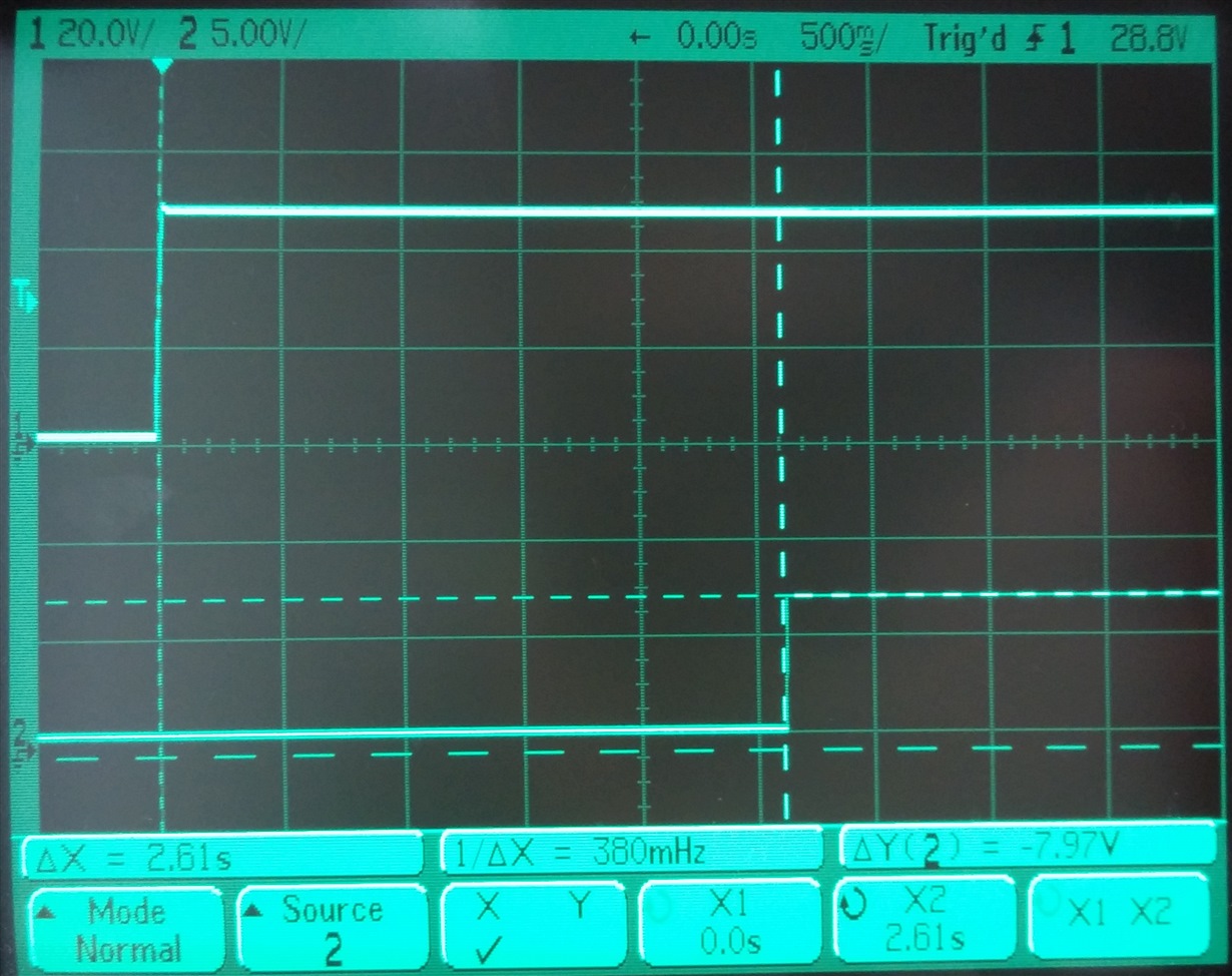
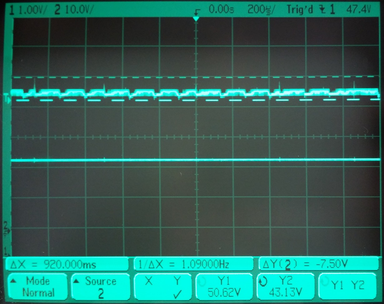
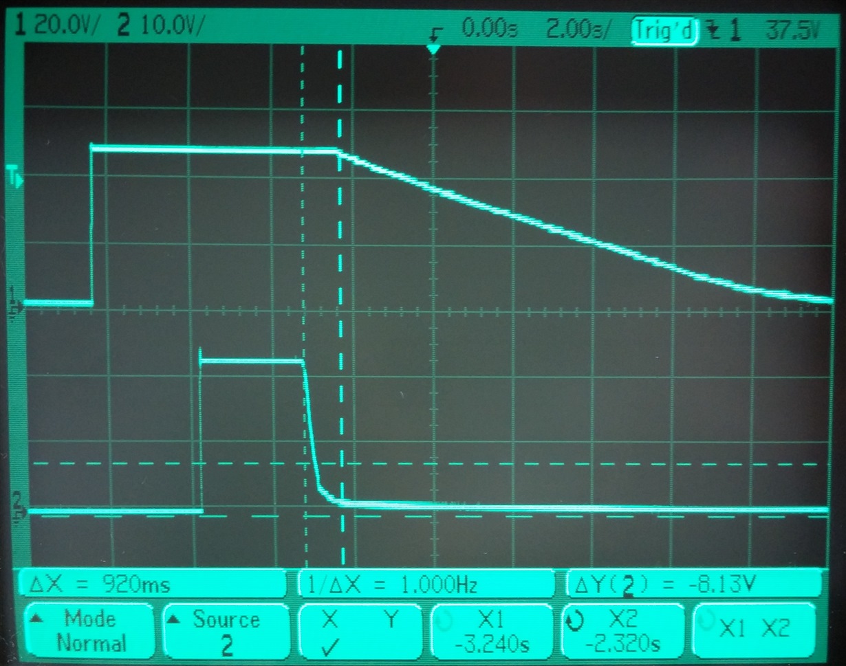
  • Find the scope captures attached, nothing special here

    Chanel 1 : 48V

    Chanel 2: 24V

    1. startup 48V

    2. Set Enable pin to 1, motor running

    3. Shut down

  • Here is something interesting though:

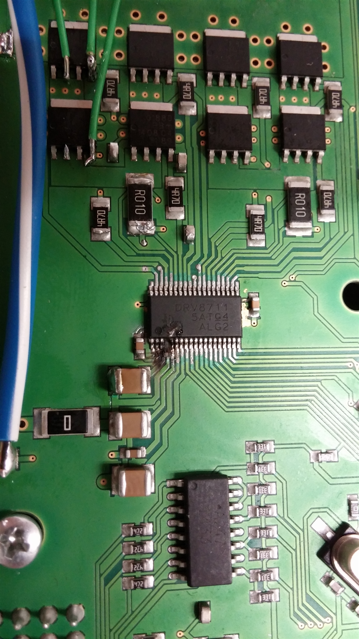
    the DRV exploded the second time, and the damage is on the same spot!
    (in the attached image it blew up a pin, the last time it was a bit more on the inside)

    ***
    TI employees: What circuitriy is in that place, and what could cause it to fail that violently?
    ***

    This has happend in a series of test, after I *decreased* the lowwer MOSFET's driving current from 200 to 100mA.
    (MOSFET was switching through in <45ns with 200mA @ 500ns)

  • Hi Ioannis,

    The damage on the driver looks like a bond wire from the VM pin to the device die may have failed. This can happen when a large amount of current is pulled through that path.

    When this failure happens what is the current being drawn out of the 48V power supply? What is the current while performing the series of tests you mentioned above?

    If you remove the driver from the board are their obvious signs of manufacturing errors? Possibly a pins shorted together, to ground, or to VM?

    Have you checked the continuity between the device pins and their respective copper pads? The photo provide looks like some pins may be floating.

    Have you tried running the driver at a lower voltage (24V) to see if the failure is replicated there?
  • Hello,

    Can this be a Short Circuit there between the pins?
    Your Chip is miss aligned. Especially where the VM pin should be.

    Regards,
    Alex
  • The operating voltage range of DRV8711 is up to 52V. This doesn't mean you can drive a motor up to 52V. There are some factors must be considered:
    (1) Any motor with coils will induce back EMF while running. You should consider to add more room for back EMF.
    (2) The built-in charge-pump will output up to 12V based on VM.

    Theoretically, if VM=48V then VCP_max=48+12=60V. If there are backEMF on VM then the voltage on VCP will be higher than 60V. This could be the reason why it gets burned.

    You also have to double check the voltage rating of all used capacitors. 100V rating may be required since it is too dangerous to use 50V rated capacitors for 48V power supply. When the operating voltage is closed to the rated voltage, the capacitance of a capacitor will decrease dramatically. So, capacitors won't work as expected.

    In summary, you have to decrease VM (voltage supply for motor).

    Since I just begin my motor-control project using F280xx and DRV83xx, I have very limited knowledge and experience of this field. Please feel free to correct me if my understanding/viewpoint is wrong.