Part Number: SRC4392
Hi All,
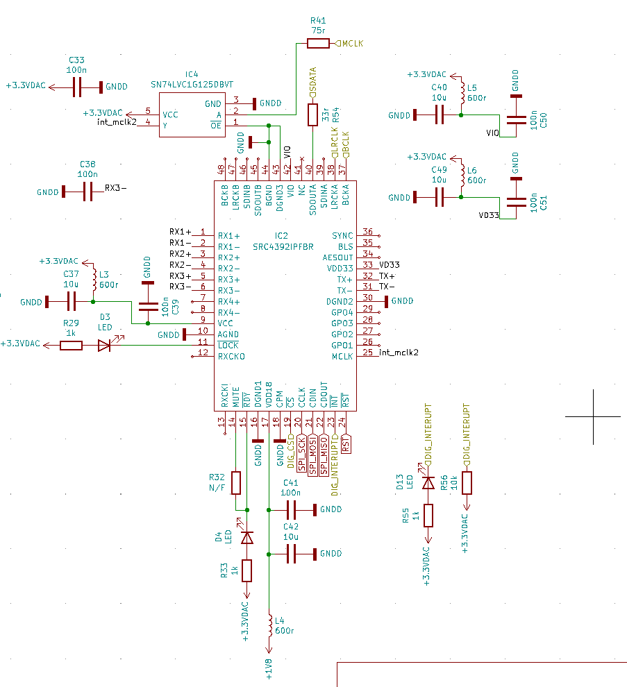
I am working on a DSP based on ADAU1466 + SRC4392, controlled by an ESP32 through SPI interface.
My programming skills are not so great, so i where wondering if anyone have a sketch they would be willing to share with me?
Currently i have tried this code which does not seem to do the trick;
#include "Arduino.h"
#include <SPI.h>
const SPISettings settingsA(1000000, MSBFIRST, SPI_MODE3);// Store SPI transaction information to settingsA

void setup() {
  Serial.begin(115200);    // Initialize the USB serial port for debug
  SPI.begin();
  pinMode(SPI_SRC, OUTPUT);
  digitalWrite(SPI_SRC, HIGH);
}
void loop() {
  initiate_src4392();
  delay(5000);
}
void initiate_src4392 () {
  write_src4392(0x7f, 0x00); // Initial write to page register, selecting page 0
  write_src4392(0x01, 0x80); // Software reset
  write_src4392(0x03, 0x31); // Port A format I2S, slave mode, src->porta
  write_src4392(0x04, 0x01); // Port A clock to MCLK/256 (48k)
  write_src4392(0x05, 0x41); // Port B format I2S, slave mode, mute output (port is not used)
  write_src4392(0x06, 0x01); // Port B clock to MCLK/256 (48k)
  //write_src4392(0x08, 0x31); // Bypass Mux RX1, AESMUX BYMUX, LDMUX BPMUX, Enable AES and TX
  write_src4392(0x0D, 0x08); // DIR reference clock = MCLK
  write_src4392(0x0E, 0x08); // Automatic DIR-mute for loss of lock
  //write_src4392(0x0F, 0x12); // Registers 0F, 10 and 11; PLL1 configuration. Values from datasheet: P=1, J=8, D=0
  //write_src4392(0x10, 0); // Registers 0F, 10 and 11; PLL1 configuration. Values from datasheet: P=1, J=8, D=0
  //write_src4392(0x11, 0); // Registers 0F, 10 and 11; PLL1 configuration. Values from datasheet: P=1, J=8, D=0
  write_src4392(0x16, 0xF4); // CRC, parity, validity, bip encoding, and dir unlock unmasked
  //write_src4392(0x18, 0xAA);	// interrupt mode to level change
  //write_src4392(0x19, 0xAA);	// interrupt mode to level change
  write_src4392(0x2d, 0x42); // Port B as input, MCLK as Ref, Mute Disabled, Volume tracking leftch.
  //write_src4392(0x30, 0x07); // Set left channel volume -3.5dB
  write_src4392(0x31, 0x07); // Set right channel volume -3.5dB
  write_src4392(0x01, 0x3f); // Activates the chip, remove RST, Enable all.
}
void write_src4392 (unsigned char address, unsigned char data) {
  Serial.print("SRC4392ing ");
  Serial.print(address, HEX);
  Serial.print(" - ");
  Serial.println(data, HEX);
  digitalWrite(SPI_SRC, LOW);        // Assert SPI slave select line (active low)
  SPI.beginTransaction(settingsA);      // Initialize SPI
  SPI.transfer(address);
  SPI.transfer(data);
  SPI.endTransaction();              // Release the SPI bus
  digitalWrite(SPI_SRC, HIGH);    // Pull up the slave select line
}


Physically checked that hardware rst pin is 3.3v, and i can program ADAU1466 through same spi interface on a different CS pin.