This thread has been locked.
If you have a related question, please click the "Ask a related question" button in the top right corner. The newly created question will be automatically linked to this question.
Hi there,
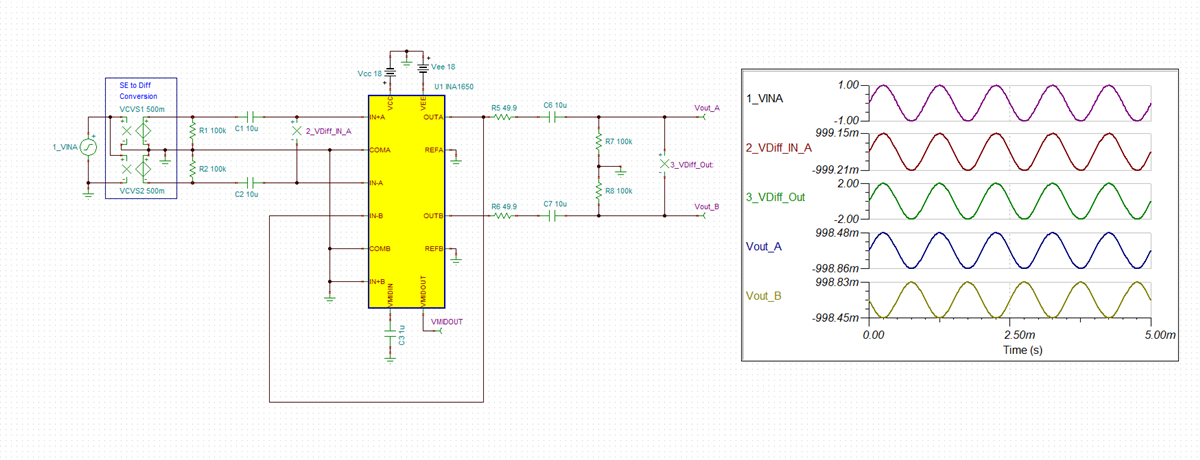
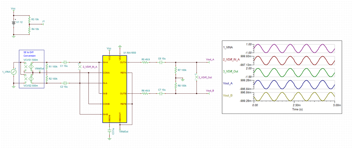
I've been looking at the INA1651 as a differential line driver. Section 8.6.2 of the data sheet shows a good example of a differential line driver with a single-ended input signal. I am wondering if you could help me design a similar circuit that accepts a differential (balanced) audio input instead. Many thanks!
Mark
Mark,
I have put together a simulation with a differential input and differential output below. Let me know what you think. I have attached the simulation file below.
Thanks, Chris!
I'm not yet familiar with the TINA-TI software. What should I adjust in order to set this up to be a unity gain system? Also, can I use this configuration with a single 12V supply (as shown in Section 8.2.2 (Figure 58) of the data sheet?
Does TI recommend any specific Capacitor & Resistor types and parameters for best operation with this device?
Thanks again.
Mark
Mark,
I have adjusted the supply to 12V single supply. Everything is now referenced to Vmid, or mid supply. I have attached the Tina simulation below. TINA-TI can be downloaded for free here:
https://www.ti.com/tool/TINA-TI
To run the transient simulation press ctrl-T. For gain bandwidth use ctrl-A and for DC analysis ctrl-D can be used.
Using this device, it will be an output of Vin*2 based on the need to use the second amplifier on chip in order to achieve the differential output. The OPA1637 is a fully differential amplifier that can be used in any desired gain. However the output current drives is not as much as the INA1650. In general thin film resistors are good to use. For high end you can use metal foil resistors. In regards to capacitors you will not want to use X7R ceramics due to the ceramic microphonic characteristics. They will act like tiny microphones in the signal path. We have a write up on capacitors in audio applications here:
Below you can see that I also adjusted the input connections of the second amplifier.