This thread has been locked.

If you have a related question, please click the "Ask a related question" button in the top right corner. The newly created question will be automatically linked to this question.

TLV320AIC1106: How to change dac volume control on the fly and switch channel from left to right or vice versa?

Part Number: TLV320AIC1106
Other Parts Discussed in Thread: TLV320AIC3106

Dear Team,

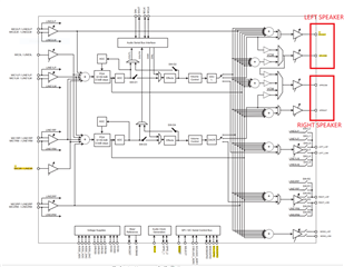
We are using TLV320AIC31106 codec for our project. As per the project we had connected two speakers in left channel connected one speaker and right other one. 

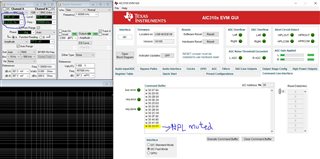
As per our project we need shift one speaker to another as per the situation (Phone application Handset and Handsfree), I had tried to mute the  LFET and Right DAC channel in the  Table 51. Page 0 / Register 43: Left DAC Digital Volume Control Register on fly.

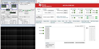
Read the register it is applying the values are not, its updated but not muted. So please provide your inputs to switch from one channel to other without disturbing the audio.

Please find the configuration details and diagram.

tlv320_codec configparam_tlv [] = {

{AIC3106_REG0_PAGESELECT, 0x00},

{AIC3106_REG0_RESET, 0x80},

{AIC3106_REG0_CODEC_SAMPLE_RATE, 0xAA},

{AIC3106_REG0_PLL_A, 0x10},

{AIC3106_REG0_PLL_B, 0x00},

{AIC3106_REG0_PLL_C, 0x00},

{AIC3106_REG0_PLL_D, 0x00},

{AIC3106_REG0_CODEC_DATAPATH, 0x0A},

{AIC3106_REG0_SERIAL_DATA_INTFC_A, 0xF0},

{AIC3106_REG0_SERIAL_DATA_INTFC_B, 0x00},

{AIC3106_REG0_SERIAL_DATA_INTFC_C, 0x08},

{AIC3106_REG0_OVERFLOW_FLAG, 0x00},

{AIC3106_REG0_DIG_FILTER_CNTL, 0x00},

{AIC3106_REG0_HEADSET_BUTTON_PRESS_A,0x00},

{AIC3106_REG0_HEADSET_BUTTON_PRESS_B,0x00},

{AIC3106_REG0_LEFT_ADC_PGA, 0x00},

{AIC3106_REG0_RIGHT_ADC_PGA, 0x00},

#if I2S_PATH_REQD

{AIC3106_REG0_MIC3LR_LEFT_ADC, 0xF0},

{AIC3106_REG0_MIC3LR_RIGHT_ADC, 0xF0},

{AIC3106_REG0_LINE1L_LEFT_ADC, 0x7C},
#else
{AIC3106_REG0_MIC3LR_LEFT_ADC, 0x00},

{AIC3106_REG0_MIC3LR_RIGHT_ADC, 0x00},

{AIC3106_REG0_LINE1L_LEFT_ADC, 0x00},
#endif

{AIC3106_REG0_LINE2L_LEFT_ADC, 0x00},

{AIC3106_REG0_LINE1R_LEFT_ADC, 0x00},

#if I2S_PATH_REQD
{AIC3106_REG0_LINE1R_RIGHT_ADC, 0x7C},

#else
{AIC3106_REG0_LINE1R_RIGHT_ADC, 0x00},
#endif

{AIC3106_REG0_LINE2R_RIGHT_ADC, 0x00},

{AIC3106_REG0_LINE1L_RIGHT_ADC, 0x00},

{AIC3106_REG0_MICBIAS, 0x40},

{AIC3106_REG0_LEFT_AGC_CNTL_A, 0x00},

{AIC3106_REG0_LEFT_AGC_CNTL_B, 0x00},

{AIC3106_REG0_LEFT_AGC_CNTL_C , 0x00},

{AIC3106_REG0_RIGHT_AGC_CNTL_A, 0x00},

{AIC3106_REG0_RIGHT_AGC_CNTL_B, 0x00},

{AIC3106_REG0_RIGHT_AGC_CNTL_C, 0x00},

{AIC3106_REG0_LEFT_AGC_GAIN, 0x00},

{AIC3106_REG0_RIGHT_AGC_GAIN, 0x00},

{AIC3106_REG0_LEFT_AGC_NOISE_GATE, 0x00},

{AIC3106_REG0_RIGHT_AGC_NOISE_GATE, 0x00},

{AIC3106_REG0_ADC_FLAG, 0x00},

#if I2S_PATH_REQD

{AIC3106_REG0_DAC_POWER_OUTPUT_DRVR, 0xE0},

{AIC3106_REG0_HI_POWER_OUTPUT_DRVR, 0x00},
#else
{AIC3106_REG0_DAC_POWER_OUTPUT_DRVR, 0x00},

{AIC3106_REG0_HI_POWER_OUTPUT_DRVR, 0x00},
#endif

{AIC3106_REG0_RESERVED_39, 0x00},

{AIC3106_REG0_HI_POWER_OUTPUT_CNTL, 0x00},

{AIC3106_REG0_DAC_OUTPUT_SWITCHING, 0x00},

{AIC3106_REG0_OUTPUT_POP_REDUCTION, 0x00},

{AIC3106_REG0_LEFT_DAC_VOLUME, 0x00},

{AIC3106_REG0_RIGHT_DAC_VOLUME, 0x00},

{AIC3106_REG0_LINE2L_TO_HPLOUT, 0x00},

#if MIC_SPKR_LOOP_BACK
{AIC3106_REG0_PGA_L_TO_HPLOUT, 0x80},
#else

{AIC3106_REG0_PGA_L_TO_HPLOUT, 0x00},
#endif

#if I2S_PATH_REQD
{AIC3106_REG0_DAC_L1_TO_HPLOUT, 0x80},
#else
{AIC3106_REG0_DAC_L1_TO_HPLOUT, 0x00},
#endif
{AIC3106_REG0_LINE2R_TO_HPLOUT, 0x00},


#if MIC_SPKR_LOOP_BACK

{AIC3106_REG0_PGA_R_TO_HPLOUT, 0x80},
#else
{AIC3106_REG0_PGA_R_TO_HPLOUT, 0x00},
#endif
{AIC3106_REG0_DAC_R1_TO_HPLOUT, 0x00},

{AIC3106_REG0_HPLOUT_OUTPUT_LEVEL, 0x09},

{AIC3106_REG0_LINE2L_TO_HPLCOM, 0x00},

{AIC3106_REG0_PGA_L_TO_HPLCOM, 0x00},

{AIC3106_REG0_DAC_L1_TO_HPLCOM, 0x00},

{AIC3106_REG0_LINE2R_TO_HPLCOM, 0x00},

{AIC3106_REG0_PGA_R_TO_HPLCOM, 0x00},

{AIC3106_REG0_DAC_R1_TO_HPLCOM, 0x00},

{AIC3106_REG0_HPLCOM_OUTPUT_LEVEL, 0x00},

{AIC3106_REG0_LINE2L_TO_HPROUT, 0x00},

{AIC3106_REG0_PGA_L_TO_HPROUT, 0x00},

{AIC3106_REG0_DAC_L1_TO_HPROUT, 0x00},

{AIC3106_REG0_LINE2R_TO_HPROUT, 0x00},

{AIC3106_REG0_PGA_R_TO_HPROUT, 0x00},
#if I2S_PATH_REQD

{AIC3106_REG0_DAC_R1_TO_HPROUT, 0x80},
#else
{AIC3106_REG0_DAC_R1_TO_HPROUT, 0x80},
#endif

{AIC3106_REG0_HPROUT_OUTPUT_LEVEL, 0x09},

{AIC3106_REG0_LINE2L_TO_HPRCOM, 0x00},

{AIC3106_REG0_PGA_L_TO_HPRCOM, 0x00},

{AIC3106_REG0_DAC_L1_TO_HPRCOM, 0x00},

{AIC3106_REG0_LINE2R_TO_HPRCOM, 0x00},

{AIC3106_REG0_PGA_R_TO_HPRCOM, 0x00},

{AIC3106_REG0_DAC_R1_TO_HPRCOM, 0x00},

{AIC3106_REG0_HPRCOM_OUTPUT_LEVEL, 0x00},

{AIC3106_REG0_LINE2L_TO_MONO_LOP, 0x00},

{AIC3106_REG0_PGA_L_TO_MONO_LOP, 0x00},

{AIC3106_REG0_DAC_L1_TO_MONO_LOP, 0x00},

{AIC3106_REG0_LINE2R_TO_MONO_LOP, 0x00},

{AIC3106_REG0_PGA_R_TO_MONO_LOP , 0x00},

{AIC3106_REG0_DAC_R1_TO_MONO_LOP, 0x00},

{AIC3106_REG0_MONO_LOP_OUTPUT_LEVEL, 0x00},

{AIC3106_REG0_LINE2L_TO_LEFT_LOP, 0x00},

{AIC3106_REG0_PGA_L_TO_LEFT_LOP , 0x00},

{AIC3106_REG0_DAC_L1_TO_LEFT_LOP, 0x00},

{AIC3106_REG0_LINE2R_TO_LEFT_LOP, 0x00},

{AIC3106_REG0_PGA_R_TO_LEFT_LOP , 0x00},

{AIC3106_REG0_DAC_R1_TO_LEFT_LOP, 0x00},

{AIC3106_REG0_LEFT_LOP_OUTPUT_LEVEL, 0x00},

{AIC3106_REG0_LINE2L_TO_RIGHT_LOP, 0x00},

{AIC3106_REG0_PGA_L_TO_RIGHT_LOP, 0x00},

{AIC3106_REG0_DAC_L1_TO_RIGHT_LOP, 0x00},

{AIC3106_REG0_LINE2R_TO_RIGHT_LOP, 0x00},


{AIC3106_REG0_PGA_R_TO_RIGHT_LOP, 0x00},

{AIC3106_REG0_DAC_R1_TO_RIGHT_LOP, 0x00},

{AIC3106_REG0_RIGHT_LOP_OUTPUT_LEVEL,0x00},

{AIC3106_REG0_MODULE_POWER_STATUS, 0x00},

{AIC3106_REG0_OUTPUT_SHORT_CIRCUIT, 0x00},

{AIC3106_REG0_STICKY_IRQ_FLAGS, 0x00},

{AIC3106_REG0_REALTIME_IRQ_FLAGS, 0x00},

{AIC3106_REG0_GPIO1_CONTROL, 0x00},

{AIC3106_REG0_GPIO2_CONTROL , 0x00},

{AIC3106_REG0_ADDNL_GPIO_CONTROL_A, 0x00},

{AIC3106_REG0_ADDNL_GPIO_CONTROL_B, 0x01},

{AIC3106_REG0_CLOCK_GEN_CONTROL, 0x02},

{AIC3106_REG0_LEFT_AGC_NEW_ATTACK, 0x00},

{AIC3106_REG0_LEFT_AGC_NEW_DECAY, 0x00},

{AIC3106_REG0_RIGHT_AGC_NEW_ATTACK, 0x00},

{AIC3106_REG0_RIGHT_AGC_NEW_DECAY, 0x00},

{AIC3106_REG0_NEW_ADC_DIGITAL_PATH, 0x00},

{AIC3106_REG0_PASSIVE_ANALOG_BYPASS, 0x00},

{AIC3106_REG0_DAC_QUIESCENT_CURRENT, 0x00}

};

  • Hi,

    Is this TLV320AIC1106 or TLV320AIC3106? The title is for AIC1106, but the diagram is for AIC3106.

    For AIC3106, are you sending your input from MIC3R/LINE3R only and enabling the left ADC path to HPL output and right ADC path to HPR output?

    Can you use the diagram above and highlight the path you want to change on the fly so it's clear?

    Basically if the path is direct as I mentioned above, you should be able to control the volume directly for example page 0 register 43 for the DAC volume and output stage volume per table 53 to each output stage and the output stage has its own gain/control like HPL in page 0 register 51 which you can mute as well.

    You can start muting say HPL using page 0 register 51 bit D3 first and then continue from there.

    Regards.

  • Dear team,

    I am using input as MIC3R and giving this DSP. The DSP will send out the data to MCU, same DSP will provide data to the codec using the path HPLOUT and HPROUT using DAC.

    So please let me know how to mute or switch the HPOUT or HPROUT. I had tried to switch using Page0 register 43 for mute DAC. But  it is not mute at any cost.

    Please note that I need to mute the DACL/R as per the project. If tried to change  register 51  why flying the codec audio output is not coming in both HPLOUT and HPROUT.

    I had tried same register 43 and 51. Please share the sample code if it is possible to switch one DAC to other DAC without effecting the audio.

    Please provide your solutions on this.

    Regards

    Nagendra

  • HI,

    See attached files which I used to check this functionality.

    I just used the DAC path from AP-PSIA to HP output since the digital audio interface will come from your MCU anyway.

    As you can see I just set the HPR /HPL to mute and the amplitude disappears in the AP analog analyzer.

    The register setting is also shown in the file.

    Below is the high level diagram showing the path with its respective register which I think can help you configure the path you desire.

    5468.TLV320AIC3106_Functional_block_Diagram_With_Registers.pdf

    Regards.

  • Dear Team,

    My issue is not resolved, still I am trying to mute the HPLOUT and HPROUT.

    Please note that I need to mute HPLOUT and Disable MIC at a time, but I am unable to do that. I had observed that when  I try to disable MIC or anything first before muting to HPLOUT, the HPLOUT and HPROUT is working normally. 

    If I mute the HPLOUT first only it is muting, please let me know is there any particular procedure is available for on fly change variables.

    At any case MIC is not going to disable state, once enable. So please provide if you have any example code on this.

    Please find the code as I written:

    /** MIC Enable */
    #define MIC_ENABLE 0x40


    #define MIC_DISABLE 0x00


    /* Un-mute the HP path */
    #define UNMUTE_HP 0x49

    /* Mute the HP path */
    #define MUTE_ON_HP 0x41

    /** Mute selection */
    #define MUTE 0x01

    /** Un-Mute selection */
    #define UNMUTE 0x00

    void hplout_mute(void)
    {
    /* Declaration of codec write variables */
    uint16_t reg_param_vol[2] = {0};

    /* Declaration codec read variable for LEFT*/
    uint8_t ldac_reg ;


    /* Assigning LEFT DAC Digital Volume Control Register address.*/
    reg_param_vol [0] = configparam_tlv[AIC3106_REG0_HPLOUT_OUTPUT_LEVEL].add;

    /** Sending the Codec LEFT Volume Setup Register address for read
    * the register value.
    */
    i2c_read_reg (CODEC_ADDRESS,&reg_param_vol,&ldac_reg,1);

    /* Providing some delay for the register write or read to codec. */
    delay();

    /* Clearing the volume as per the MUTE basis */
    ldac_reg = (ldac_reg) & (~MUTE_ON_HP);

    /* Assigning LEFT DAC Digital Volume Control Register address.*/
    reg_param_vol [0] = configparam_tlv[AIC3106_REG0_HPLOUT_OUTPUT_LEVEL].add;

    /* Assigning The LEFT DAC channel for mute condition.*/
    configparam_tlv[AIC3106_REG0_HPLOUT_OUTPUT_LEVEL].data = ldac_reg|MUTE_ON_HP;

    /* Assigning LEFT DAC Digital Volume Control Register address.*/
    reg_param_vol [0] = configparam_tlv[AIC3106_REG0_HPLOUT_OUTPUT_LEVEL].add;

    /* Assigning register data value to codec varaible. */
    reg_param_vol [1] =  configparam_tlv[AIC3106_REG0_HPLOUT_OUTPUT_LEVEL].data;

    /* Sending register address and data using I2C to codectlv320.*/
    i2c_write_reg (CODEC_ADDRESS,&reg_param_vol,2);

    /* Providing some delay for the register write or read to codec. */
    delay();

    }

    void hprout_unmute(void)
    {
    /* Declaration of codec write variables */
    uint16_t reg_param_vol_right[2];

    /* Declaration codec read variable for RIGHT */
    uint8_t rdac_reg ;

    uint8_t mic_reg ;

    /* Assigning LEFT DAC Digital Volume Control Register address.*/
    reg_param_vol_right [0] = configparam_tlv[AIC3106_REG0_HPROUT_OUTPUT_LEVEL].add;

    /** Sending the Codec LEFT Volume Setup Register address for read
    * the register value.
    */
    i2c_read_reg (CODEC_ADDRESS,&reg_param_vol_right,&rdac_reg,1);

    /* Providing some delay for the register write or read to codec. */
    delay();

    /* Clearing the volume as per the MUTE basis */
    rdac_reg = (rdac_reg) & (~MUTE_ON_HP);

    /* Assigning LEFT DAC Digital Volume Control Register address.*/
    reg_param_vol_right [0] = configparam_tlv[AIC3106_REG0_HPROUT_OUTPUT_LEVEL].add;

    /* Assigning The LEFT DAC channel for mute condition.*/
    configparam_tlv[AIC3106_REG0_HPROUT_OUTPUT_LEVEL].data = rdac_reg;

    /* Assigning LEFT DAC Digital Volume Control Register address.*/
    reg_param_vol_right [0] = configparam_tlv[AIC3106_REG0_HPROUT_OUTPUT_LEVEL].add;

    /* Assigning register data value to codec varaible. */
    reg_param_vol_right [1] = configparam_tlv[AIC3106_REG0_HPROUT_OUTPUT_LEVEL].data;

    /* Sending register address and data using I2C to codectlv320.*/
    i2c_write_reg (CODEC_ADDRESS,&reg_param_vol_right,2);

    /* Providing some delay for the register write or read to codec. */
    delay();
    }

    void mic_selection (void)
    {
    /* Declaration of codec write variables */
    uint16_t reg_param_mic[2] = {0};

    /* Declaration codec read variable for MIC*/
    uint8_t mic_reg ;

    /* Assigning LEFT DAC Digital Volume Control Register address.*/
    reg_param_mic [0] = configparam_tlv[AIC3106_REG0_MICBIAS].add;

    /** Sending the Codec LEFT Volume Setup Register address for read
    * the register value.
    */
    i2c_read_reg (CODEC_ADDRESS,&reg_param_mic,&mic_reg,1);

    /* Providing some delay for the register write or read to codec. */
    delay();

    /* Clearing the volume as per the MUTE basis */
    mic_reg = (mic_reg) & (~MIC_DISABLE );

    /* Assigning The LEFT DAC channel for mute condition.*/
    configparam_tlv[AIC3106_REG0_MICBIAS].data = mic_reg |MIC_DISABLE;

    /* Assigning LEFT DAC Digital Volume Control Register address.*/
    reg_param_mic [0] = configparam_tlv[AIC3106_REG0_MICBIAS].add;


    /* Assigning register data value to codec varaible. */
    reg_param_mic [1] = (configparam_tlv[AIC3106_REG0_MICBIAS].data);

    /* Sending register address and data using I2C to codectlv320.*/
    i2c_write_reg (CODEC_ADDRESS,&reg_param_mic,2);

    /* Providing some delay for the register write or read to codec. */
    delay();

    }

    Please let me know any changes I need to do.

  • Hi,

    There's no particular sequence to mute/unmute HP output.

    Attached here is the settings I used to enable MIC3L/R to HPL/R output. In my testing I sent the digital input data from MIC3 back to digital output and I just mute/unmute the respective block.

    test on EVM.pdf

    # Device Address, Register Address, Data (all in hex)
    w 30 11 0F
    w 30 12 F0
    w 30 16 7C
    w 30 13 7C
    w 30 0F 00
    w 30 10 00
    w 30 19 80
    w 30 07 8A
    w 30 29 02
    w 30 2B 00
    w 30 0E C0
    w 30 25 E0
    w 30 26 10
    w 30 2F 80
    w 30 40 80
    w 30 41 0D
    w 30 33 0D
    

    Regards,

    Peter

  • Dear Team,

    It seems register address are different, please use the attached manual for register address and let me know the exact setting using some sample code.

    tlv320aic3106.pdf

  • Hi,

    As mentioned in the comment above, the values are in hex where else the register address in datasheet is in decimal. They are the same register address.

    Something in your system prevents the muting/unmuting.

    Regards,

    Peter