This thread has been locked.
If you have a related question, please click the "Ask a related question" button in the top right corner. The newly created question will be automatically linked to this question.
Hi,
we are now quite some time failing to startup the TAS5733L Amplifier without having it set the error register bit for overcurrent/undercurrent or temperature fault, although everything we can measure seems within recommendations, so we would appreciate very much any help and pointers!
Layout looks like this, we can measure i2s at 3.078Mhz when we do stream after startup sequence, we do measure 3.3V / 12V and do adhere to the minimum wait times depicted in TI datasheet document.
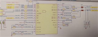
So we are probably complying with the necessary clock rates (mclk "faked" by connecting to SCLK).
We exported Configuration from PP3 application, and are simply applying it trying to adhere to the datasheet by placing trim oscillator and an appropriate wait time at the top instead of the order that comes from the PP3 export (where trim is called in the middle of config settings).
If needed we can also send an image of the oscilator showing the timing of pins nRST, nPDN, 3V3 and 12V, but they should be complying absolutely with datasheet requirements (always maintaining minimum times and low/high barriers).
Hello,
Can you provide the startup waveforms? Additionally, can you confirm what resistors are populated on the output for R714-718 on your board. If you disconnect from the output filter are you still seeing this fault triggered?
Is this seen on multiple boards? If you resolder a new IC on your board are you seeing this same issue?
best regards,
Luis
Hi, Louis - will be back in a few minutes with a screenshot of the startup waveform and the resistor info. We do see the same fault on multiple boards, but did not try to resolder a new IC until now. For some more info - we are on a Linux system, so very very tight time contraints would put us into a bad situation, but I don't think this should be the problem at all in the end, also we have (due to having big condensators on the 12V line) a non-zero base-line for the PVDD but it's always a good chunk below the 6V mentioned in the datasheet. We also tried with that line starting at 0 to no avail. Maybe that one (pics are coming in next post) though could be the "interesting" one because it ramps up quite slowly and in steps.
Hi, we tried first to disconnect from the output filter - it seems this is definetely related, we can start the amp without further modification in software now and the error register stays at zero. We will now try to add piece by piece back on the pcb and report back at which point we'll get the error back.
After we disconnected the Output Filter the error was gone. So we looked further into it. We Changed the application to work in Stero mode. In that mode we also had no error and also could play music through Channel A and B.
This led us to the solution PBTL mode could not be recognized. We looked again into our Application and found Resistor R703 to be too high with its 100kR. We reduced it to 42kR and finaly the error was gone and the Amp also worked in PBTL mode.
We totaly overlooked that the High Level input current of the digital Inputs could drain up to 75uA.
Thank you for your help. The hint with the output Filter led us to the right solution.