This thread has been locked.
If you have a related question, please click the "Ask a related question" button in the top right corner. The newly created question will be automatically linked to this question.
Hi Team,
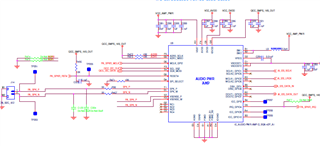
We are using a TAS2559 Audio amplifier in our design. We could hear noise in between audio intervals(during pause). I have attached schematics for your reference. Kindly help to clear this issue. Is there any filter to be added in output?
Hi Manikandan,
Could you share more details about the test/problem?
Best regards,
-Ivan Salazar
Applications Engineer
What is the noise like?------> Yes, it is like continuous random noise. Attached recording.
Are the clocks enabled all the time during pause? Can you also inspect digital input data line during pause?------> BCLK enabled all the time. LRCK and data disabled during the pause.
Power sequence--> VBAT-> IOVDD->DVDD->AVDD
Please share the initialization script for TAS2559---> We are using below ROM Mode 1 configuration script generated from PPC3.
######################################################### # TAS2559 debug cfg file # PPC3 File: # TAS2559 version: 3.0.5 # DDC Name: ESRDFJGH ######################################################### d 01 w 98 00 00 w 98 7f 64 w 98 07 01 d 10 w 98 7f 00 w 98 07 03 w 98 00 00 w 98 7f 00 w 98 2c 00 w 98 00 00 w 98 7f 00 w 98 04 60 d 02 w 98 05 00 w 98 00 00 w 98 04 00 w 98 00 00 w 98 7f 00 w 98 01 01 d 10 # PLL begins w 98 00 00 w 98 7f 00 w 98 00 01 w 98 73 0f w 98 74 00 w 98 00 00 w 98 7f 64 w 98 1b 01 w 98 1c 10 w 98 1d 00 w 98 1e 00 w 98 20 02 w 98 22 08 w 98 02 10 w 98 21 08 w 98 01 08 w 98 2b 00 w 98 2c 40 w 98 1f 20 w 98 2a 00 # PLL ends # Program begins w 98 00 00 w 98 7f 00 w 98 00 fd w 98 0d 0d w 98 00 fe w 98 28 00 w 98 00 00 w 98 08 02 w 98 0a 08 w 98 34 03 w 98 00 32 w 98 3c 3d > 99 > 99 > 9a w 98 70 00 > 03 > de > 00 w 98 68 00 > 00 > 00 > 00 w 98 00 33 w 98 64 39 > 80 > 00 > 00 w 98 00 35 w 98 4c 00 > 00 > 00 > 01 w 98 00 34 w 98 68 00 > 6a > e2 > 36 w 98 6c 00 > 6a > e2 > 36 w 98 70 7f > 2a > 3b > 94 w 98 00 00 w 98 22 01 w 98 00 00 w 98 7f 82 w 98 00 19 w 98 38 d1 > 50 > 00 > 10 w 98 00 00 w 98 7f 00 w 98 00 32 w 98 3c 3d > 99 > 99 > 9a > 30 > 00 > 00 > 00 > 50 > 00 > 00 > 00 w 98 4c 02 > 00 > 00 > 00 w 98 60 28 > 00 > 00 > 00 w 98 00 33 w 98 40 00 > 00 > 00 > 00 w 98 64 39 > 80 > 00 > 00 w 98 00 00 w 98 06 7c w 98 2b 03 w 98 2a 04 w 98 00 00 w 98 7f 64 w 98 28 80 w 98 00 00 w 98 7f 00 w 98 08 02 w 98 00 33 w 98 10 73 > 33 > 33 > 33 > 6b > 85 > 1e > b8 w 98 20 1d > 99 > 99 > 99 > 20 > cc > cc > cc > 24 > 00 > 00 > 00 > 27 > 33 > 33 > 33 > 2a > 66 > 66 > 66 > 2d > 99 > 99 > 99 > 30 > cc > cc > cc > 34 > 00 > 00 > 00 # Program ends # PRE begins w 98 00 00 w 98 7f 00 w 98 2f 2a w 98 2d 17 w 98 00 02 w 98 06 01 w 98 00 32 w 98 54 00 > 88 > 3f > d1 > 00 > 06 > d3 > 72 # PRE ends # Configuration begins # Configuration ends w 98 00 00 w 98 7f 00 w 98 05 a0 w 98 04 f2 d 02 w 98 00 00 w 98 7f 00 w 98 2d 21 w 98 2e 21 w 98 2c 0b # PostPowerUp begins # PostPowerUp ends d 02 w 98 00 00 w 98 7f 00 w 98 07 00 w 98 7f 64 w 98 07 00
The resistors in output are 0 ohms and capacitors are not populated. One more thing need in this, we can hear noise immediately after powering up TAS2559 . Except for audio playing time, we can hear the noise.
Also, do we have to write I2C Configurations each time?. Because if we are not writing I2C there is no audio output. In between time(During pause/ no audio), we can hear noise
Hi Manikandan,
Thanks for sharing additional information.
I'll check your script and similar sequence on my side.
You would need to write I2C config every time as long as clocks are disabled. When the device is no longer getting input clocks it should detect clock error.
Clock error should mute the device, so I need to understand why there is still something coming out on the speaker at that time.
Best regards,
-Ivan Salazar
Applications Engineer
Adding a case:
1) If we are programming the same script to our custom board using TAS2559 EVM through PPC3. we are not getting this noise.Is the PPC3 Tool programs any additional script during initialization?.
Hi Manikandan,
What file are you using on your end system to configure TAS2559? EVM use cfg format so I wonder what format are you using on your custom board.
You can also compare a register dump for both configurations to understand what could be adding to the noise.
Best regards,
-Ivan Salazar
Applications Engineer
We are using above attached combined configuration_rom_mode1 .cfg file generated from PPC3.
Used direct I2C in PPC3 to write same code in custom board
Could you help out with reasons that leads to noise during mute interval??
Hi Manikandan,
You may be configuring the device in RAM mode (or tuning mode) by using PPC3. I could replicate the random noise by either using your script, or by PPC3 -> Test and Measurement -> ROM Mode 1 or 2, then disable the input clocks.
It seems the configuration for ROM mode is not muting the device when input clocks are lost. I can check further on the differences.
Are you planning to use TAS2559 in ROM mode or Tuning mode? If using Tuning mode this should not be an issue.
Best regards,
-Ivan Salazar
Applications Engineer
Could you share any document for programming methods for TAS2559 or even a script that works without noise? ROM Mode 1 or 2 is better, even if it works in RAM Mode, it's okay. We will try that.
Hi Manikandan,
You can try with the attached cfg.
8664.combined_configuration_0_TuningMode_48KHz.cfg
Alternatively follow either of these procedures:
Best regards,
-Ivan Salazar
Applications Engineer