Other Parts Discussed in Thread: TAS2560
Hello,
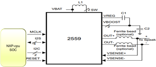
For one of our Embedded Project to port Android system on imx8mp NXP chipsets, we have a customized Target hardware which supports TAS2559YZ Audio-amplifier.
The imx8mp NXP-processor acts as HOST and provides SAI (Serial audio interface) and I2C interfaces to TAS2559 Amplifier.
imx8mp acts as I2C Master and TAS 2559 is I2C slave (address-0x4C) on i2c bus.
In order to have proper hardware configuration in kernel Device tree file (.dts), We have downloaded TI data sheet for tas2559to study the features & configurations of the audio-device and also downloaded TI-supplied TAS2559 Android driver package from Git repository https://git.ti.com/cgit/tas2557sw-android/tas2559-android-driver/tree?h=master
The Host-device connection has MCLK --> to tas2559 MCLK1_GPI2 pin and I2S signals are connected to (BCLK1_GPIO1, WCLK1_GPIO2,DIN1_GPI1, DOUT1_GPIO3) as inputs.
The Reset from imx8mp SOC is directly connected to tas2559 RESET and tas2559 interrupt pin is not used.
Please clarify the following DTS entries highlighted in Yellow. What does each of these entries mean ?
We are not using any GPIO pin for Reset and Interrupt. In such a case, do we have to retain these entries or we can remove these entries? pls advice.
and if these entries are removed from dts file, does it cause any drive-probe function failure?
tas2559@4c{
#sound-dai-cells = <1>;
compatible = "ti,tas2559";
reg = <0x4c>;
ti,tas2559-reset-gpio = <&msmgpio 13 0>;
ti,tas2560-reset-gpio = <&msmgpio 73 0>;
ti,tas2559-irq-gpio = <&msmgpio 59 0>;
ti,tas2560-irq-gpio = <&msmgpio 82 0>;
ti,tas2559-addr = <0x4c>;
ti,tas2560-addr = <0x4d>;
ti,tas2559-channel = <0>; /* 0, left; 1, right */
ti,tas2560-channel = <1>; /* 0, left; 1, right */
ti,ycrc-enable = <1>; /* 0, disable; non-zero, enable */
ti,echo-ref = <0>; /* 0, left channel; 1, right channel; 2, both */
ti,bit-rate = <16>; /* 16, 20, 24, 32 */
status = "ok";
};