This thread has been locked.

If you have a related question, please click the "Ask a related question" button in the top right corner. The newly created question will be automatically linked to this question.

TLV320AIC3254: Input Signal level Limitation for AGC

Other Parts Discussed in Thread: TLV320AIC3254, TLV320AIC3254EVM-K
  • Part Number: TLV320AIC3254

Hi 

Regarding this thread,  its input signal level formula is as follows : 

input_level (in dBFS) + max_pga <  target-level +3.9dB

We would like to know if there are any known issues and limitations with the AGC when input signal exceeds the formula.

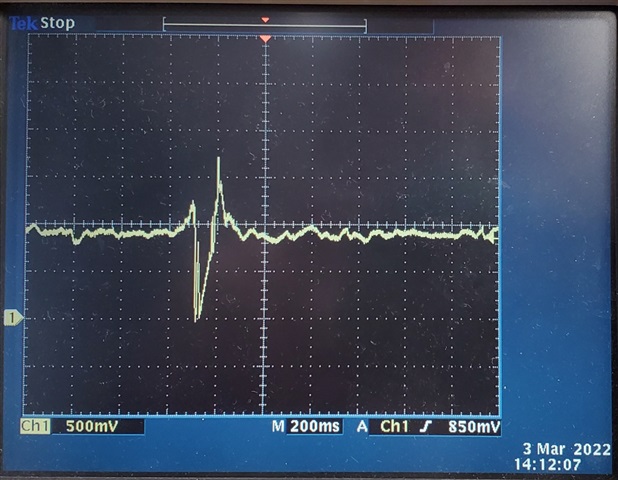
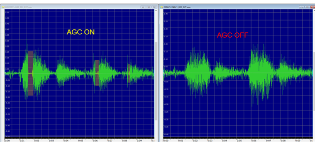
We thought that if the input signal was large and exceeds the formula, the AGC output should be clipped, but the problem we encountered was that when the input signal was large, the AGC output went to zero level.

You could see the following screenshot for ADC output:

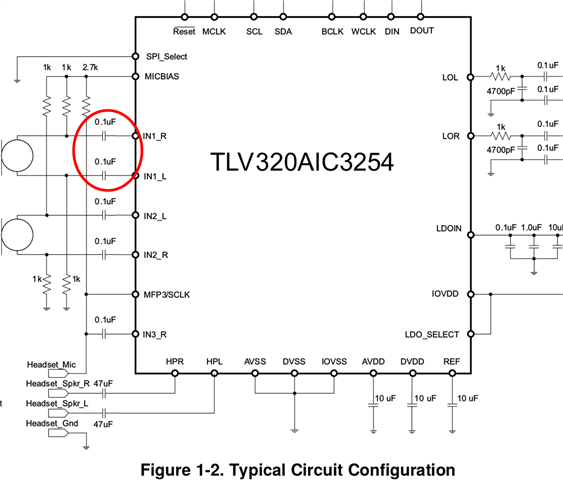
We also measure our input signal :
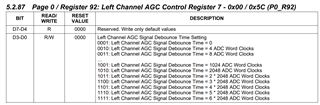
Our AGC configuration as follows:
AGC target level :  -5.5dB
Noise Threshold :  -62dB
Max Gain :  16dB
Do you have any suggestion for us?
Thank.
BR
Trevor
  • Hi,

    That formula is when a low frequency sinewave is used, in your case it looks like just normal input from a microphone.

    It should not shut off the output when input exceeds the target level, have you tried with different attack/decay time?

    Regards.

  • Hi pdjuandi, 

    1. That formula is when a low frequency sine wave is used >>>> Do you know where to find this limitation? We would like to know if there are other limitation on AGC?

    2. Our signal frequency is around 200Hz ~ 400Hz, which is a low frequency signal.

    3. The following screenshot is our input signal, could you help us to check if our signal amplitude exceeds the specification of AGC?

    4. We have tried to adjust the AGC Signal Debounce Time to 4 second, and to monitor the Page 0 / Register 74 D6 & D5. Regarding our input signal(you could refer the following screenshot), the pulse width is around 100mS , in this case , we read the Page 0 / Register 74, the D6 & D5 always return 1, it means the signal power was lower than Noise Threshold, but we still encounter the problem(he AGC output went to zero level.)

    5. We did some experiments, you could see the following figure(Typical Circuit Configuration), it used a 0.1uF capacitor, because of our microphone specs, we need to use 22uF capacitor. the results of our experiments are shown below. Do you have any suggestions for us?

    TLV320AIC3254EVM-K + 0.1uF + Our Microphone  >>>>>> The AGC Output is normal 

    TLV320AIC3254EVM-K + 22uF + Our Microphone    >>>>>> The AGC Output is abnormal 

    Custom Board + 0.1uF + Our Microphone     >>>>>>>  The AGC Output is normal 

    Custom Board + 22uF + Our Microphone     >>>>>>>  The AGC Output is abnormal 


    BR
    Trevor
  • Hi,

    1. I'm checking internally for the references and will get back to you on this.
    2. For MIC input they are usually low as in human voice but not of a sinewave tone.
    3. What signal is this as it's about 1V and above the input ADC 0.5Vrms?
    4. Page 0 register 74 is the beep generator and signal debounce time is register 92 a function of wclk, are these status or data registers you are referring to?

             5. The capacitor used will form a high pass filter into the analog input. Please refer to section 11.2.2 of this document and it also gives you suggestion when input is higher than 0.5Vrms.

    https://www.ti.com/lit/ds/symlink/tlv320aic3254.pdf?ts=1646409357365&ref_url=https%253A%252F%252Fwww.ti.com%252Fproduct%252FTLV320AIC3254%253FkeyMatch%253DAIC3254

  • Hi Pdjuandi, 

    We got around 1M ohm when measured by an ohm meter at IN1_R, and it combined with 0.1uF input capacitor, so it formed a C, R high pass filter (cutoff frequency 1.59Hz),

    Are the resistance of IN1_R and high pass filter calculation all correct?

    The analog microphone recommended output capacitor is 2.2uF, how do we select input capacitor of IN1_R for the single-end analog microphone,

    the symptom is AGC processing signal might block continuous loud signal when IN1_R input capacitor high than 0.1uF, 

    and due to our application required capture 20~200Hz audio signal, so that we tried to select a bigger capacitor as possible 

    BR,

    Ethan

  • Hi,

    The equivalent resistance calculation and the cutoff frequency are provided in section 11.2.2.1. It will depend on your RIN and gain settings.

    You can use that to calculate the cutoff frequency or capacitance for the MIC input.

    Regards.