This thread has been locked.

If you have a related question, please click the "Ask a related question" button in the top right corner. The newly created question will be automatically linked to this question.

TAS2505: no output sound issue

Part Number: TAS2505

Hi team,

my customer found there's no sound output, and we don't have EVM to debug now 

would you help debug on this? they're quite urgent 

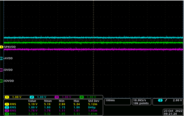
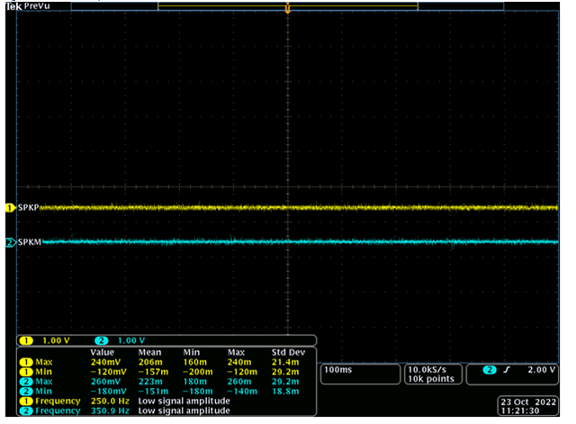
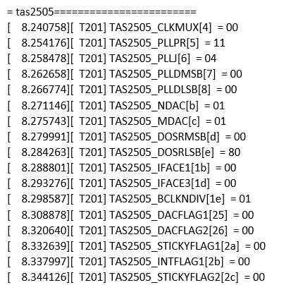
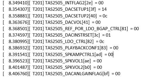
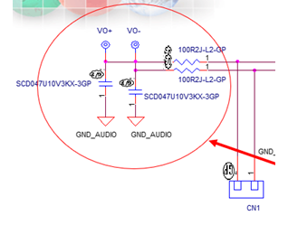
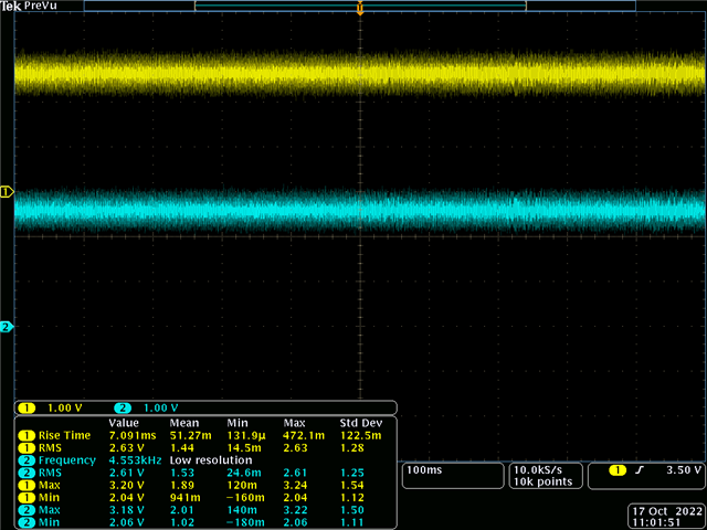
below is the schematic , I2C log and output waveform,

they measure at this two point  after low pass,

  • Hi Fred,

    I've got some questions on the schematic and test:

    • Schematic shows LDOSEL pin 8 connected to 1.8V which is not even the same level as IOVDD 3.3V? Actually this pin should be connected to same potential as SPKVDD, as we do on the EVM.
      Perhaps internal LDO is not properly powering up thus analog portion of the device is not working as expected? Can you inspect all power supplies with scope? (SPKVDD, AVDD, DVDD, IOVDD)
    • I see two different scope captures, what does VIP3 mean? In one of the captures there seems to be a ramp waveform, is this just GND noise of some sort?
    • Could you please also test by disconnecting the outputs and measure just out of the Class-D pins from TAS2505? you can remove L1/L2 and use the scope on those pads. Is the Class-D switching after I2C initialization?

    Best regards,
    -Ivan Salazar
    Applications Engineer

  • Hi Ivan,

    they connect LDO_SEL to  SPKVDD, but still no change.

    but I'm confused that datasheet say LDO_SEL should connect to GND

    I'll update the rest you requested later

  • Hi Fred,

    Can you please also share the input clock frequencies to double check the register configuration? We'll need MCLK (if used), BCLK and WCLK.

    Regarding the LDO_SEL pin, at some point we encouraged customers to not use the internal LDO due to some known issue that affected a few devices in some specific application conditions. This is being handled on a new revision that will be released soon.
    However if your problem is observed on all units, then it should not be related to this LDO and you should still be able to use it.

    Best regards,
    -Ivan Salazar
    Applications Engineer

  • Hi Ivan,

    have you looked into the I2C log?

    our register 48 is defaulted muted, is this the problem?

    update the voltage you want,

  • Hi Fred,

    After review of the I2C log, it doesn't seem right:

    • As you mentioned, Class-D is not enabled
    • DAC is not enabled either, this is controller by register 0x3f
    • As part of DAC initialization, they need to enable MDAC and NDAC as well for the internal clocks, those are not enabled
    • If they share the mentioned I2S clocks, I can verify if default clock tree settings would be OK for them

    They can use the GUI example script as baseline:

    Fullscreen
    1
    2
    3
    4
    5
    6
    7
    8
    9
    10
    11
    12
    13
    14
    15
    16
    17
    18
    19
    20
    21
    # Playback Class-D
    # Page switch to Page 0
    W 30 00 00
    # Assert Software reset
    W 30 01 01
    # Page Switch to Page 1
    W 30 00 01
    # LDO output programmed as 1.8V and Level shifters powered up.
    W 30 02 00
    # Page switch to Page 0
    W 30 00 00
    # Dac Instruction programming PRB #1
    W 30 3c 01
    # CODEC_CLKIN=MCLK.MCLK should be 12.288MHz
    W 30 04 00
    # Codec Interface control Word length = 16bits.BCLK&WCLK inputs.I2S mode.
    W 30 1b 00
    # Data slot offset 00
    W 30 1c 00
    # DAC NDAC Powered up, NDAC=1
    W 30 0b 81
    XXXXXXXXXXXXXXXXXXXXXXXXXXXXXXXXXXXXXXXXXXXXXXXXXX

    Best regards,
    -Ivan Salazar
    Applications Engineer