This thread has been locked.

If you have a related question, please click the "Ask a related question" button in the top right corner. The newly created question will be automatically linked to this question.

ADC5140EVM-PDK: How to use AGC on ADC5140EVM-PDK

Part Number: ADC5140EVM-PDK
Other Parts Discussed in Thread: PUREPATHCONSOLE

This is a question about how to use the ADC5140EVM-PDK evaluation board.

I use PurePathConsole to connect the EVM and the PC, and record the audio input to the EVM on the PC.

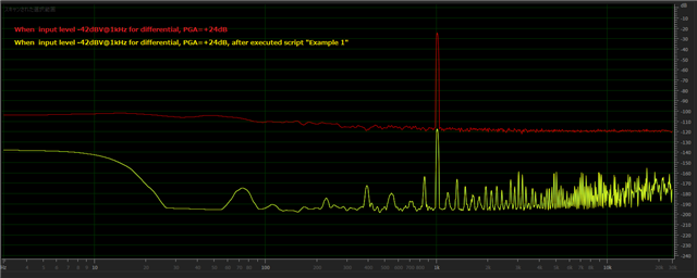
I changed the Channel Gain (PGA) on PurePathConsole and confirmed that it was reflected in the recorded data, but the characteristics did not change whether AGC was enabled or disabled. (Input level is -42dBV to -16dBV for differential input. PGA setting is 24dB, AGC setting is default value Tagget level=-34dB, Max gain allowed=24dB)

When AGC operates, the expected value is that the output level will be constant in a certain input section, but it will behave as if AGC is not applied.

Also, in the register tool, Set Bit0 of CH1_CFG0 Register (page = 0x00, address = 0x3C) to 1, I set Bit3 of DSP_CFG1 Register (page = 0x00, address = 0x6C) to 1, but AGC did not work. Are there any other registers that should be changed?

  • Hi,

    Good question, it is possible that the noise threshold default value is too low so it can distinguish your input range from noise. I would suggest changing the value in this register to see if that impacts the output level (page = 0x05, address = 0x20.)

    Also reference this application note on configuring AGC: Using the Automatic Gain Controller in TLV320ADCx140 

    There are two example scripts on page 10-11, I suggest running or modifying these scripts to see if you get the desired output.

    Let me know if this works for you, if not can you provide a register dump so we can troubleshoot from there.

  • Thank you for your reply.

    Since the input level is at least -42dBV, if the initial value of Noise Threshold is -90dB, I think it is high enough for AGC to work.

    When I ran Example 1 on page 10 of the document you introduced, the output level dropped by more than 90dB. (Use I/O of I2C monitor of PurePathConsole)

    Also, even if the above script is executed, it is not reflected in the PurePathConsole's GUI.Recording data that compared executed script or not. Is it a specification that PurePathConsole's register map is only Page.0?

    Either way, I'm having trouble because it doesn't work as expected.

  • dump.csv

    script example1.txt
    w 98 00 00 # Goto Page 0
    w 98 02 81 # Wake-up device by I2C write into P0_R2 using internal AREG
    w 98 02 81 # Exit Sleep mode
    d 10 # Wait for 16 ms
    w 98 6C 48 # Enable AGC in DSP_CFG1
    w 98 3C 01 # Select AGC on Ch. 1 using CH1_CFG0
    w 98 41 01 # Select AGC on Ch. 2 using CH2_CFG0
    w 98 74 01 # Select AGC on Ch. 3 using CH3_CFG0
    w 98 75 01 # Select AGC on Ch. 4 using CH4_CFG0
    w 98 70 E7 # AGC LVL = -36 dB, AGC GAIN = 24 dB
    w 98 00 05 # Goto Page 5
    w 98 7C 7F B5 16 50 # AGC Release Time Alpha
    w 98 00 05 # Goto Page 6
    w 98 08 00 4A E9 B0 # AGC Release Time Beta
    w 98 0C 50 FC 64 5C # AGC Attack Time Alpha
    w 98 10 2F 03 9B A4 # AGC Attack Time Beta
    w 98 18 00 00 02 00 # AGC Attack Debounce
    w 98 1C 00 04 B0 00 # AGC Release Debounce
    w 98 20 FF FF A6 00 # AGC Noise Threshold : -90 dB
    w 98 44 00 04 B0 00 # AGC Noise Debounce
    w 98 3C 00 00 01 00 # AGC Attack Hysteresis
    w 98 34 00 00 03 00 # AGC Release Hysteresis
    w 98 54 00 00 04 00 # AGC Noise Hysteresis : 4 dB
    w 98 78 7F 7F D2 B4 # AGC HPF B0
    w 98 7C 80 80 2D 4C # AGC HPF B1
    w 98 00 06 # Goto Page 6
    w 98 54 7E FF A5 68 # AGC HPF A1
    w 98 00 00 # Goto Page 0
    w 98 07 30 # TDM Mode with 32 Bits/Channel
    w 98 73 f0 # Enable Ch.1 - Ch.4
    w 98 74 f0 # Enable ASI Output channels
    w 98 75 e0 # Power up ADC

    script executed and dump data

  • Hi Hiroki, 

    Try increasing the AGC target level to -14dBFs and setting the maximum PGA gain and see how this impacts AGC output. I will get my hands on an EVM tomorrow to replicate your setup.

    Kind regards,

  • Thank you for your reply.

    As you suggested, I set the AGC target level to -14dBFS and the maximum PGA gain to +42dB, but the result was the same.

    I have verified that the register has changed. 

    Please check on your EVM, thank you.

  • Hi Hiroki,

    The audio team and I are working to see a positive indication that the AGC is working at any target level but are experiencing the same issue. Please give us more time to troubleshoot the problem, we will provide an update later this week.

    Kind regards,

  • Thank you for proceeding with the analysis. additional information.

    When I checked the operation of DRE, which is the same feedback system as AGC,

    it seemed to work. Hope this helps.


  • Hi,

    Apologies for the delay, please be patient as we're still testing.

  • Hi Hiroki,

    To provide an update, We are doing some additional testing on AGC today and if we don't see desired output we will connect with systems engineers that have developed the device's architecture for additional guidance

  • Hi Hiroki,

    I've been able to test the AGC working on the EVM. I suggest you power off/on device before testing again. My testing was as follows:

    In PPC3, load 4-CH differential MIC preset, enable AGC in audio config tab. Set target level in AGC tab, set max gain allowed = 42dB.

    I applied signal at 1kHz frequency from 10 mVrms to 2 VRms (max full scale signal). Tested from -36dB: 6dB, all with max gain set at 42dB and saw desired output +/- 2.5dbFs.

    Attached is register dump excluding default values:

    # CHECKSUM 189
    # Generated by ADCx140EVM-SW v3.0.5
    # TLV320ADC5140 device configuration
    # -----------------------------------------------------------------------------
    # Reset
    # -----------------------------------------------------------------------------
    # Select Page 0
    w 98 00 00
    # Reset Device
    w 98 01 01
    # 1mS Delay
    # -----------------------------------------------------------------------------
    # Begin Device Memory
    # -----------------------------------------------------------------------------
    # Page 0 (0x00) Dump
    # Select Page 0
    w 98 00 00
    # Wake up and enable AREG
    w 98 02 81
    # GPI Configuration
    w 98 3b 60
    # Channel 1 configuration
    w 98 3c 81
    # Channel 2 configuration
    w 98 41 81
    # Channel 3 configuration
    w 98 46 81
    # Channel 4 configuration
    w 98 4b 81
    #DSP configuration
    w 98 6c 48
    # AGC configuration
    w 98 70 ed
    # Channel Input/Output Configuration
    w 98 74 f0
    # Page 4 (0x04) Dump
    # Select page 4
    w 98 00 04
    # High pass filter coefficients
    w 98 49 e6
    > 48
    > c6
    > 80
    w 98 4d 19
    > b7
    > 3a
    > 7f
    w 98 51 cc
    > 91
    > 8b
    > 24
    w 98 55 46
    > c8
    > 84


    Let me know if this helps.

    Regards,

  • Thank you for confirmation. I will check tomorrow.

    One question is that the Input Type on PCC3 is set to "Microphone", but does it need to be set to "Microphone" in order to use AGC?

    Also, how does the operation of the IC change between "Microphone" and "Line"?

  • When I verified with the method you taught me, I found that AGC works, but I was able to guess the cause of the problem that AGC does not work.

    Probably, but I suspect that saving and loading settings in a .ppc3 file will cause AGC to stop working.

    Could you please try to reproduce it under the following conditions?

    1. Connect EVM and PC via USB

    2. Load Preset "4 channel Diffrectoral Line Input" in PPC3

    3. Set AGC to Signal Target Level=-6dB, Max Gain Allowed=42dB, and enable AGC

    4. Set to Active and record on PC → AGC operates

    5. Save this setting to a .ppc3 file

    6. Disconnect and connect EVM and PC with USB

    7. Load the .ppc3 file from step 5

    8. Set to Active and record on PC → AGC does not work

    There was no difference in the value dumped by reading the register in procedure 4 and procedure 8. (Check page.0 only)

  • In addition, if there is a way to dump registers other than page.0 on PPC3, please let me know.

  • Hi Hiroki,

    Followed proedure outline and AGC operates. Whether I uploaded the saved ppc3 file or dumped all registers, AGC operates.

    To dump all registers and all pages, after configuring device, go to "End System Integration" tab, uncheck the skip registers box.

    I did direct i2c write of the following code after disabling power and clocks and AGC operates:

    # CHECKSUM 251
    # Generated by ADCx140EVM-SW v3.0.5
    # TLV320ADC5140 device configuration
    # -----------------------------------------------------------------------------
    # Reset
    # -----------------------------------------------------------------------------
    # Select Page 0
    w 98 00 00
    # Reset Device
    w 98 01 01
    # 1mS Delay
    # -----------------------------------------------------------------------------
    # Begin Device Memory
    # -----------------------------------------------------------------------------
    # Page 0 (0x00) Dump
    # Select Page 0
    w 98 00 00
    # Wake up and enable AREG
    w 98 02 81
    w 98 05 05
    # ASI Configuration
    w 98 07 30
    w 98 08 00
    w 98 09 00
    # ASI Channel Configuration
    w 98 0b 00
    w 98 0c 01
    w 98 0d 02
    w 98 0e 03
    w 98 0f 04
    w 98 10 05
    w 98 11 06
    w 98 12 07
    # Master mode configuration
    w 98 13 02
    w 98 14 48
    # Clock Configuration
    w 98 16 10
    # PDM Configuration
    w 98 1f 40
    w 98 20 00
    # GPIO Configuration
    w 98 21 22
    # GPO Configuration
    w 98 22 00
    w 98 23 00
    w 98 24 00
    w 98 25 00
    w 98 29 00
    # GPI Configuration
    w 98 2b 00
    w 98 2c 00
    w 98 32 00
    w 98 33 ff
    w 98 3b 60
    # Channel 1 configuration
    w 98 3c 81
    w 98 3d 00
    w 98 3e c9
    w 98 3f 80
    w 98 40 00
    # Channel 2 configuration
    w 98 41 81
    w 98 42 00
    w 98 43 c9
    w 98 44 80
    w 98 45 00
    # Channel 3 configuration
    w 98 46 81
    w 98 47 00
    w 98 48 c9
    w 98 49 80
    w 98 4a 00
    # Channel 4 configuration
    w 98 4b 81
    w 98 4c 00
    w 98 4d c9
    w 98 4e 80
    w 98 4f 00
    # Channel 5 configuration
    w 98 52 c9
    w 98 53 80
    w 98 54 00
    # Channel 6 configuration
    w 98 57 c9
    w 98 58 80
    w 98 59 00
    # Channel 7 configuration
    w 98 5c c9
    w 98 5d 80
    w 98 5e 00
    # Channel 8 configuration
    w 98 61 c9
    w 98 62 80
    w 98 63 00
    #DSP configuration
    w 98 6b 01
    w 98 6c 48
    # DRE configuration
    w 98 6d 7b
    # AGC configuration
    w 98 70 0d
    # Channel Input/Output Configuration
    w 98 73 f0
    w 98 74 f0
    # Page 2 (0x02) Dump
    # Select page 2
    w 98 00 02
    # Biquad 1 coefficients (N0, N1, N2, D1, D2)
    w 98 08 7f
    > ff
    > ff
    > ff
    w 98 0c 00
    > 00
    > 00
    > 00
    w 98 10 00
    > 00
    > 00
    > 00
    w 98 14 00
    > 00
    > 00
    > 00
    w 98 18 00
    > 00
    > 00
    > 00
    # Biquad 2 coefficients
    w 98 1c 7f
    > ff
    > ff
    > ff
    w 98 20 00
    > 00
    > 00
    > 00
    w 98 24 00
    > 00
    > 00
    > 00
    w 98 28 00
    > 00
    > 00
    > 00
    w 98 2c 00
    > 00
    > 00
    > 00
    # Biquad 3 coefficients
    w 98 30 7f
    > ff
    > ff
    > ff
    w 98 34 00
    > 00
    > 00
    > 00
    w 98 38 00
    > 00
    > 00
    > 00
    w 98 3c 00
    > 00
    > 00
    > 00
    w 98 40 00
    > 00
    > 00
    > 00
    # Biquad 4 coefficients
    w 98 44 7f
    > ff
    > ff
    > ff
    w 98 48 00
    > 00
    > 00
    > 00
    w 98 4c 00
    > 00
    > 00
    > 00
    w 98 50 00
    > 00
    > 00
    > 00
    w 98 54 00
    > 00
    > 00
    > 00
    # Biquad 5 coefficients
    w 98 58 7f
    > ff
    > ff
    > ff
    w 98 5c 00
    > 00
    > 00
    > 00
    w 98 60 00
    > 00
    > 00
    > 00
    w 98 64 00
    > 00
    > 00
    > 00
    w 98 68 00
    > 00
    > 00
    > 00
    # Biquad 6 coefficients
    w 98 6c 7f
    > ff
    > ff
    > ff
    w 98 70 00
    > 00
    > 00
    > 00
    w 98 74 00
    > 00
    > 00
    > 00
    w 98 78 00
    > 00
    > 00
    > 00
    w 98 7c 00
    > 00
    > 00
    > 00
    # Page 3 (0x03) Dump
    # Select page 3
    w 98 00 03
    # Biquad 7 coefficients
    w 98 08 7f
    > ff
    > ff
    > ff
    w 98 0c 00
    > 00
    > 00
    > 00
    w 98 10 00
    > 00
    > 00
    > 00
    w 98 14 00
    > 00
    > 00
    > 00
    w 98 18 00
    > 00
    > 00
    > 00
    # Biquad 8 coefficients
    w 98 1c 7f
    > ff
    > ff
    > ff
    w 98 20 00
    > 00
    > 00
    > 00
    w 98 24 00
    > 00
    > 00
    > 00
    w 98 28 00
    > 00
    > 00
    > 00
    w 98 2c 00
    > 00
    > 00
    > 00
    # Biquad 9 coefficients
    w 98 30 7f
    > ff
    > ff
    > ff
    w 98 34 00
    > 00
    > 00
    > 00
    w 98 38 00
    > 00
    > 00
    > 00
    w 98 3c 00
    > 00
    > 00
    > 00
    w 98 40 00
    > 00
    > 00
    > 00
    # Biquad 10 coefficients
    w 98 44 7f
    > ff
    > ff
    > ff
    w 98 48 00
    > 00
    > 00
    > 00
    w 98 4c 00
    > 00
    > 00
    > 00
    w 98 50 00
    > 00
    > 00
    > 00
    w 98 54 00
    > 00
    > 00
    > 00
    # Biquad 11 coefficients
    w 98 58 7f
    > ff
    > ff
    > ff
    w 98 5c 00
    > 00
    > 00
    > 00
    w 98 60 00
    > 00
    > 00
    > 00
    w 98 64 00
    > 00
    > 00
    > 00
    w 98 68 00
    > 00
    > 00
    > 00
    # Biquad 12 coefficients
    w 98 6c 7f
    > ff
    > ff
    > ff
    w 98 70 00
    > 00
    > 00
    > 00
    w 98 74 00
    > 00
    > 00
    > 00
    w 98 78 00
    > 00
    > 00
    > 00
    w 98 7c 00
    > 00
    > 00
    > 00
    # Page 4 (0x04) Dump
    # Select page 4
    w 98 00 04
    w 98 08 7f
    > ff
    > ff
    > ff
    w 98 0c 00
    > 00
    > 00
    > 00
    w 98 10 00
    > 00
    > 00
    > 00
    w 98 14 00
    > 00
    > 00
    > 00
    w 98 18 00
    > 00
    > 00
    > 00
    w 98 1c 7f
    > ff
    > ff
    > ff
    w 98 20 00
    > 00
    > 00
    > 00
    w 98 24 00
    > 00
    > 00
    > 00
    w 98 28 00
    > 00
    > 00
    > 00
    w 98 2c 00
    > 00
    > 00
    > 00
    w 98 30 7f
    > ff
    > ff
    > ff
    w 98 34 00
    > 00
    > 00
    > 00
    w 98 38 00
    > 00
    > 00
    > 00
    w 98 3c 00
    > 00
    > 00
    > 00
    w 98 40 00
    > 00
    > 00
    > 00
    w 98 44 7f
    > ff
    > ff
    > ff
    # High pass filter coefficients
    w 98 48 7f
    > e6
    > 48
    > c6
    w 98 4c 80
    > 19
    > b7
    > 3a
    w 98 50 7f
    > cc
    > 91
    > 8b
    w 98 54 24
    > 46
    > c8
    > 84
    # Power up/down
    # Select page 0
    w 98 00 00
    w 98 75 60


  • Thank you for confirmation.

    It means that the above procedure did not reproduce the phenomenon that AGC does not work.

    I will check the differences in the registers on other pages using the method you taught me.

    My question is, if I write directly with I2C, the changed values are reflected in the PPC3 register map, but are they not reflected in the GUI?

  • With direct write of I2C it wont reflect in the GUI instantly but if you unplug then plug usb cable back into port  PPC3 will prompt you to overwrite GUI with device values

  • I have checked with the method you suggested.

    ・When operating in step 4

    ・When operated in step 8

    ・Write the register dump provided by your company with I2C

    There was no register difference for all pages in the above three cases.

    Next, we investigated the behavior when the USB cable of PPC3 was plugged and unplugged.

    After loading the setup file saved in step 5, AGC did not work even when PPC3 was enabled.

    After that, when I unplugged and plugged in the USB and selected "Update GUI with device value", AGC didn't work.

    However, when I unplugged the USB again and selected "Overwrite device with GUI values", AGC worked.

    In conclusion, in order to apply the setup file and operate AGC, after loading the setup file, I found it necessary to unplug and plug the USB and select "Overwrite device with GUI values".

    Is the above procedure correct for using PPC3?

  • I will ask a question on the assumption that AGC is operating according to the above procedure.

    What is the relationship between PGA (Channel Gain) and Max Allowed Gain during AGC operation?

    AGC settings are Target Level = -6dBFS, Max Allowed Gain = 42dB,

    The output level according to the PGA setting when the input is -62dBV differential input is described.

    PGA=0dB … Output Level = -26dBFS

    PGA=6dB …Output Level=-43dBFS

    PGA=12dB … Output Level=-43dBFS

    PGA=18dB …Output Level=-43dBFS

    PGA=24dB …Output Level=-43dBFS

    PGA=30dB … Output Level=-38dBFS

    PGA=36dB … Output Level = -32dBFS

    PGA = 42dB … Output Level = -26dBFS

    Since the PGA setting during AGC operation is controlled with the upper limit of Max Allowed Gain, I thought that the PGA setting would be invalid, but why does the output level change when the PGA is changed?

  • Hi,

    Digital filters, Biquads, AGC, or DRE all manipulate the PGA gain. User can program PGA to a fixed value, then AGC target level and max gain are decreasing or increasing the PGA value to meet target level. Please reference app note: Using the Automatic Gain Controller in TLV320ADCx140 ,it details the limitations of the AGC and when it is advisable to use maximum gain depending on your input signal. There are example scripts at the end and AGC results in different scenarios throughout the guide for more context.

    Regards,

  • Thank you for your reply. I have read the document you provided.

    I understood how to use the setting value related to AGC, but I didn't understand the relationship with the fixed value of PGA when AGC was enabled.

    For the measurement example shown above, what is the formula for calculating the actual PGA gain?

    Based on that, what value would you expect to be set?

    AGC settings are Target Level = -6dBFS, Max Allowed Gain = 42dB, The output level according to the PGA setting when the input is -62dBV differential input is described.

    ---

    PGA=0dB … Output Level=-26dBFS

    PGA=6dB …Output Level=-43dBFS

    PGA=12dB … Output Level=-43dBFS

    PGA=18dB …Output Level=-43dBFS

    PGA=24dB …Output Level=-43dBFS

    PGA=30dB … Output Level=-38dBFS

    PGA=36dB … Output Level=-32dBFS

    PGA = 42dB … Output Level = -26dBFS

    ---

  • Hi Hiroki,

    When setting a fixed PGA value you can validate it through output dB = 20*log(Gain)/Vrms Full-scale . Subsequently 10^(Output dBFs/20) * 2 = Input Vrms. When disabling AGC/DRE I have validated this to be true.

    The AGC will attenuate or gain the PGA value up to max allowed gain (42 dB) but there are limitations to signals it recognizes when doing so. Example 1 &2 scripts of app note highlight that a high maximum gain is not always recommended so as the PGA value and target value change you will see varying results.

    Kind Regards,