This thread has been locked.

If you have a related question, please click the "Ask a related question" button in the top right corner. The newly created question will be automatically linked to this question.

PCM5122: Minimum I2C sequence to get standard I2S output in slave mode

Part Number: PCM5122
Other Parts Discussed in Thread: TLV320ADC5140, PCM5102, PCM5102A

Our I2S Master is the TLV320ADC5140.  Here is our TLV startup sequence for this example, 96khz.  We can successfully capture audio, however when trying to play back via the PCM5122 on the same PCB, there is no audio output on OUTL or OUTR. 

Our I2S lines look like this: BCK 24.576mhz, SCK (from XO): 24.576mhz, LRCK/FSYNC: 96khz.  DIN on the PCM5122 shows the playback signal. Again, no analog audio output with i2c sequence below.

ADR1 is HI, ADR2 is LO, giving us i2c base address of 0x4D.  It seems we can successfully communicate with both the TLV320ADC5xxx (I2C 0x4C) and PCM5122 (0x4D) on the same i2c bus.

Here is the last I2C sequence we tried (this is being run *after* starting up the TLV ADC I2S Master).  We're trying the simplest method; just the bare minimum to make the DAC work.

w 77 reg 0x2 val 0x10 b10000
w 77 reg 0x1 val 0x11 b10001
w 77 reg 0x2 val 0x0 b0
w 77 reg 0xd val 0x0 b0
w 77 reg 0xe val 0x0 b0
w 77 reg 0xe val 0x2 b10
w 77 reg 0x25 val 0x7d b1111101
w 77 reg 0x28 val 0x3 b11
w 77 reg 0x3d val 0x30 b110000
w 77 reg 0x3e val 0x30 b110000
w 77 reg 0x41 val 0x0 b0
w 77 reg 0x2 val 0x0 b0

Are we missing something?  For reference, here is the ADC's I2C startup sequence:

w 76 reg 0x2 val 0x91 b10010001
w 76 reg 0x13 val 0x87 b10000111
w 76 reg 0x14 val 0x58 b1011000
w 76 reg 0x21 val 0xa0 b10100000
w 76 reg 0x7 val 0x87 b10000111
w 76 reg 0xb val 0x20 b100000
w 76 reg 0xc val 0x20 b100000
w 76 reg 0xd val 0x0 b0
w 76 reg 0xe val 0x0 b0
w 76 reg 0x3d val 0x0 b0
w 76 reg 0x42 val 0x0 b0
w 76 reg 0x47 val 0x0 b0
w 76 reg 0x4c val 0x0 b0
w 76 reg 0x6b val 0x4 b100
w 76 reg 0x3c val 0xb8 b10111000
w 76 reg 0x41 val 0xb8 b10111000
w 76 reg 0x46 val 0xb8 b10111000
w 76 reg 0x4b val 0xb8 b10111000
w 76 reg 0x76 val 0xf0 b11110000
w 76 reg 0x73 val 0xf0 b11110000
w 76 reg 0x74 val 0xf0 b11110000
w 76 reg 0x75 val 0x60 b1100000

  • It seems that the DAC needs to see the standard ratio on the I2S lines but we still have a major problem which is that we can't capture when the DAC has an acceptable ratio.  It seems weird that the ADC as I2S master is creating a BCK of 24.576 rather than our expected 96k * 32 * 2 (6.144mhz).  When we set TLV320's reg 0x14 FS_BCLK_RATIO to 64 it generates a proper (normal?) I2S BCK which the PCM5122 understands fine; the playback of a recorded 96k pcm file is perfect.  However, then we can't capture from the ADC.  It almost seems like there's an issue with more slots on the I2S line rather than 2 (left and right)?  When we record on the ADC with register 0x14's FS_BCLK_RATIO at 4d (64) all we get is static on the left channel.  We need to switch FS_BCLK_RATIO to 256 (at 96k) in order to record in stereo.

    Is this a result of using 4-into-2 mode? I don't recall this being an issue with 4-into-2 mode of AKM ADC chips.  Could it be that the TLV320ADC's CLK_SRC register is required?

    Any help from the TI team would be greatly appreciated.

  • Hi Aaron,

    So if I understand correctly you have 2 situations:

    1. With some ADC5140 configuration you can record audio (in some host controller) but you cannot playback the same data through PCM5122
    2. With other ADC5140 configuration you can playback through PCM5122 but you cannot record audio (again, in some host controller)

    Is that correct?

    Can you confirm how are you configuring the Tx data from ADC5140 for each case?
    Notice that, at least on the attached config for PCM5122. the format is set to I2S, thus the DAC is expecting the L data to be located at the beginning of the frame and then R data after half of the whole word, ie. 32 bits for a ratio of 64 and 128 bits for a ratio of 256. Whereas TDM/DSP format expected L and R data to be consecutive, ignoring the rest of the bits before or after the set of 64 bits, depending on the offset bits configuration.

    From the system perspective, do you need only two channels? Or do you require 8 channels for a bit ratio of 256?
    If only need stereo, I think it would be just a matter of making sure ADC5140 and the host controller which is recording the data, to have the same configuration. It seems PCM5122 is already working OK in that case.

    Best regards,
    -Ivan Salazar
    Applications Engineer

  • Hi Ivan,

    Thank you.  The goal is just stereo I2S.  The only unique part of that is we aren't quite sure what to do with our 4-into-2 on the ADC input.

    Currently, on ASI_OUT_CH_EN we're using 11110000.  Then, with our 24.576mhz clock we ended up with the ratio of 64 on register 0x14 which is somewhat confusing:

    (to ADC5140):

    w 76 reg 0x13 val 0x87 b10000111
    w 76 reg 0x14 val 0x54 b1010100
    w 76 reg 0x21 val 0xa0 b10100000

    With this, we have the expected I2S BCK of 6.144mhz (96000 * 32 * 2).  Now recording works at 96k as expected, and that same file plays back on the PCM5122 without a problem.  I think we're still very unsure if our 4-into-2 implementation is correct on the ADC5140.

    Here's the ADC schematic for reference:

    Lastly, there seems to be some faint hiss on the PCM5122 analog output even when no data is being received.  We don't recall hearing this with the PCM5102 and wonder if there is some analog gain issue we need to address in the DAC's registers.  It's very faint; but the PCM5102A was dead silent even without XSMT.

  • Hi Aaron,

    I'm not very clear on the 4-into-2 input to ADC. Is it that connection you have from the same source to IN1 and IN2, and similarly for IN3 and IN4?
    Then you confirm stereo I2S is the goal, so why have all 4 channels with analog input, and also enable 4 ASI channels on register 0x74? For stereo you would only need 2.
    In addition, it may seem channel output configuration is not correct:

    • Register 0x0b and 0x0c set to 0x20 mean the output data would be using the same slot
    • Register 0x0d and 0x0e set to 0x00 also mean output data would be using the same slot
    • Register 0x07 set to 0x87
      • bits 7-6 set '10' mean format is LJF, please confirm this is correct
      • bits 5-4 set '00' mean slot length of 16bit, which makes sense by ratio = 64 = 4 * 16, you may need 32bit instead for stereo and keep the same ratio

    So based on all that, I would suggest to configure the device for only two channels in register 0x74 and 0x73, then select different slots for each register 0x0b and 0x0c, and select proper slot length and format in register 0x07.

    Best regards,
    -Ivan Salazar
    Applications Engineer

  • Hi Ivan,

    Re: I2S vs LJ see 3.2 here: https://www.ti.com/lit/an/sbaa382/sbaa382.pdf

    Do you know if anyone at TI might know how 4-into-2 should work with regard to I2C/config? The datasheet states:

    "111-dB, DRE disabled, 2-channel summing"

    I'm just not sure how exactly that should be configured aside from the analog side.

  • Hi,

    Our TI experts are out of office today for US holiday so please be patient as responses may be delayed.

    Thank you for your patience.

    Regards,

  • Hi Aaron,

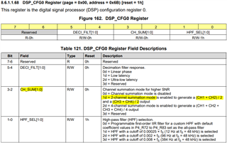
    The summing configuration is detailed in D/S section 8.3.6.6: https://www.ti.com/lit/ds/symlink/tlv320adc5140.pdf#page=35
    You may be looking specifically for mode '01':

    However, your schematic suggests IN1 and IN2 both have the same input signal, the same for IN3 and IN4. So my question is would you be summing two signals which are actually the same?

    Best regards,
    -Ivan Salazar
    Applications Engineer

  • Hi Aaron, 

    Thanks for the additional information. So the reason is to use the 3dB SNR boost in the summing feature, that's clear now.

    Let us know if there are any further questions.

    Best regards,
    -Ivan Salazar
    Applications Engineer