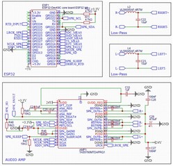
I created a PCB with the TAS5760MD audio amplifier and this worked perfectly but when I created a second version with some added features unrelated to the amplifier and copied the previous schematic, this new version constantly gives a clock error, given by the fault register. I checked the different clock signals with an oscilloscope and compared these with the previous working version but they look the same. Even using the same software and microcontroller and making multiple PCBs to make sure there is no soldering error, I still get the same problem. The PCB traces are only a couple centimeters long and I tried adding capacitors but without success. Is there any special reason why this error could show up?
-
Ask a related question
What is a related question?A related question is a question created from another question. When the related question is created, it will be automatically linked to the original question.


