- Ask a related questionWhat is a related question?A related question is a question created from another question. When the related question is created, it will be automatically linked to the original question.
This thread has been locked.
If you have a related question, please click the "Ask a related question" button in the top right corner. The newly created question will be automatically linked to this question.
Hello together,
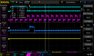
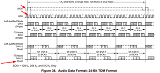
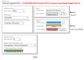
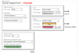
we use an PCM1840 as ADC while we are using the PCM1690 as DAC. For the PCM1840, we have configured it in Slave Mode (4-channel output with time division multiplexing (TDM) mode). For the PCM1690, we have configured it in Slave Mode 24-Bit I2S mode TDM format. Pictures below show our configuration.
The clocks are shared between ADC and DAC and driven by a DSP which acts as clock master. We wonder a bit because it seems that the PCM1690 requires a positive BCLK while the PCM1840 seems to need a negative BCLK.
- Q1: Can you let us know at which clock transition the bits are sampled in the PCM1840 and PCM1690?
What we did to make it work is the following.
On the DSP data output we send the data in I2S mode with the clock set to negative polarity. Bits are sampled on the positive to negative transition. So this should perfectly fits the PCM1690 specifications, but those clocks are send to the PCM1840 as well, except for SDATA of course. On the DSP data input side, we sample left-justified. At the moment we sample here also on the positive to negative transition.
- Q2: Would it make here more sense to sample on the negative to positive transition (Thats why we would need to know the sample point of the PCM1840)?
- Q3:So far all of this seem to work, but we would want to know if you see any potential risks here as the clock requirements of both chips seem to differ?
PCM1840


PCM1690


DSP Settings:
Apart from this topic, we have sometimes a strange behaviour with the PCM1840.
When we boot up the system, it seems that it takes sometimes super long for the ADC to lock to the clocks. We rechecked the bootup behaviour and everything seems to be like specified, except for 2 points:
- Point 1 and Q4: Is that the BCLK has a negative polaritiy instead of a positive, as described above. Could this cause such a problem?
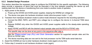
- Point 2 and Q5: The clocks are running before we release the ADC from Reset. In Page 28 of the datasheet it is mentioned that the clocks should be first active after step a. Is this really required? As this is not that easy when the ADC runs in slave mode.
Best regards,
Eric
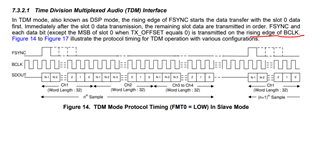
The data is sampled on the rising edge of BCLK in PCM1840.
Have you tried toggling SHDNZ once again?
Perhaps the clock determination unit may need to stop the timings a moment and restart to trigger another estimation of input timing.As a test please remove and return the timings to see if stable output rerturns faster
Hey Sanjay,
on the bootup i keep the device under restet with holding SHDNZ down. But of course i can try to release it once and toggle it afterwards.
- But in general you see no potential risk in using PCM1840 and PCM1690 in combination as i described?
- Also considering that the clock polarity is different?
Best regards,
Eric
Unfortunately I am not a specialist on the PCM1690.
I am refering this to our DAC Specialist
Hello Eric and Sanjay,
As far as the DAC goes, the requirements are clear and it needs to trigger on the rising edge of BCLK . The rising edge of each LRCLK is the start of each frame and the new set of data is triggered at that rising edge. if you can trick any of these 2 ICs to see the clks the way they expect, I don't think you will have a potential issue of getting out of sync over time since you are using the same clks fet to both IC, although i am not familiar with the ADC (PCM1840).
Regards,
Arash