This thread has been locked.

If you have a related question, please click the "Ask a related question" button in the top right corner. The newly created question will be automatically linked to this question.

TAS2780: Required 8-channel interface?

Part Number: TAS2780

Does the I2S/TDM interface to this device require all 8 channels or can you send data for 1 channel only?

I see the demo sends data for 8 channels between FSYNC pulses. We are trying to send data for only 1 channel since we don't need more than one channel, but as of now it doesn't appear to be working. 

  • Hi Kevin,

    this device can support UP TO 8 channels but less TDM time slots can be used. I believe the lowest used will be standard I2S which has only L and R channels.

    Can you share more details on what you are doing and what is not working?

    Regards,

    Arthur

  • Thanks for the clarification. I assumed this was the case but wasn't sure since it currently isn't working and the "UP TO" didn't appear to be called out in the datasheet. 

    I'm glad you pointed out the I2S lowest standard includes a L/R channel. We are currently only sending data for one channel so it could be this is not compliant. 

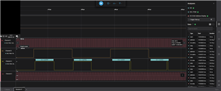
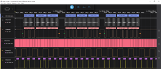
    This is what we are currently sending (16-bit word in a 32-bit frame).

    Let me know your thoughts.

  • Hi Kevin,

    At first glance your TDM signals look to be OK. what is your I2C address?

    by default the device will be selecting the data slot equal to its I2C address offset. this means that 0x70 will take slot 0, 0x72 will take slot 1, 0x74 will take slot 2 etc. 

    in your case If the settings in register 0x0A where left un-touched then the correct I2C address is 0x70

    Regards,
    Arthur

  • Thanks for the information we are getting static now. Any chance you can provide an example PCM audio file? This is our first time working with digital audio so we are not sure if what we are sending will actually sound good.

  • Hi Kevin, 

    Here is an example uncompressed audio file we would use for testing. we will play a .wav file either through a windows audio player which will send data via USB to our EVM, then convert it to I2S. or we will use an I2S master from our "Audio Precision" test equipment directly.  

    Can you share with me a dump of all the book 0 page 0 registers? so when the system is enabled and you hear static, please read all the registers and share it with me. I will check some of the I2S related registers and see if the settings are correct

    Regards,
    Arthur

  • The EVM has its setup done from an external source so the J23 v& J24 jumpers are set to EXT as well as J7 being shorted.  I don't suppose that can be changed while the board is still powered on and then be able to easily read the registers from PurePath Console 3?

  • Hi Tony, 

    You don't necessarily need to install jumper J7 to use external sources. J23/24 can be removed 'on-the-fly' these are just toggling enable pins on two different buffers. I think it may work to change the jumpers and then read from PPC3.

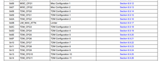
    Specifically what i want to check the is the "TDM_CFG" registers. register fields that start with 'RX_" will be settings related to the I2S receiver. I want to check and make sure the settings related to the Fs, Slot lengths, clock edges and data slots are matching the I2S screenshot you shared

    Regards,
    Arthur

  • OK, that seemed to work!  I just never felt safe changing a jumper while a PCB was powered up.  Anyway, here is the export from the Register Map applet:

    Device Page Register Address Register Name Register Value
    Channel-1 Book0_Page0 0x00 Page 0x00
    Channel-1 Book0_Page0 0x01 Software Reset 0x00
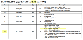
    Channel-1 Book0_Page0 0x02 Device Operational Mode 0x13
    Channel-1 Book0_Page0 0x03 Channel Settings 0x88
    Channel-1 Book0_Page0 0x04 DC Blocker Register0 0x60
    Channel-1 Book0_Page0 0x05 DC Blocker Register1 0x41
    Channel-1 Book0_Page0 0x06 Misc Configuration1 0x00
    Channel-1 Book0_Page0 0x07 Misc Configuration2 0x20
    Channel-1 Book0_Page0 0x08 TDM Configuration0 0x38
    Channel-1 Book0_Page0 0x09 TDM Configuration1 0x02
    Channel-1 Book0_Page0 0x0A TDM Configuration2 0x12
    Channel-1 Book0_Page0 0x0B Limiter Max Attenuation 0x80
    Channel-1 Book0_Page0 0x0C TDM Configuration Reg3 0x00
    Channel-1 Book0_Page0 0x0D TDM Configuration Reg4 0x32
    Channel-1 Book0_Page0 0x0E TDM Configuration Reg5 0x44
    Channel-1 Book0_Page0 0x0F TDM Configuration Reg6 0x40
    Channel-1 Book0_Page0 0x10 TDM Configuration Reg7 0x04
    Channel-1 Book0_Page0 0x11 TDM Configuration Reg8 0x05
    Channel-1 Book0_Page0 0x12 TDM Configuration Reg9 0x06
    Channel-1 Book0_Page0 0x13 TDM Configuration Reg10 0x08
    Channel-1 Book0_Page0 0x14 TDM Configuration Reg11 0x0a
    Channel-1 Book0_Page0 0x15 ICC Configuration2 0x00
    Channel-1 Book0_Page0 0x16 TDM Configuration Reg12 0x12
    Channel-1 Book0_Page0 0x17 ICLA Configuration0 0x0c
    Channel-1 Book0_Page0 0x18 ICLA Configuration1 0x00
    Channel-1 Book0_Page0 0x19 Diagnostics Configuration0 0x0d
    Channel-1 Book0_Page0 0x1A Digital Volume Control 0x00
    Channel-1 Book0_Page0 0x1B Limiter Configuration0 0x62
    Channel-1 Book0_Page0 0x1C Limiter Configuration1 0x32
    Channel-1 Book0_Page0 0x1D BOP Configuration0 0x40
    Channel-1 Book0_Page0 0x1E BOP Configuration1 0x32
    Channel-1 Book0_Page0 0x1F BOP Configuration2 0x02
    Channel-1 Book0_Page0 0x20 BOP Configuration3 0x06
    Channel-1 Book0_Page0 0x21 BOP Configuration4 0x2c
    Channel-1 Book0_Page0 0x22 BOP Configuration5 0x4c
    Channel-1 Book0_Page0 0x23 BOP Configuration6 0x20
    Channel-1 Book0_Page0 0x24 BOP Configuration7 0x02
    Channel-1 Book0_Page0 0x25 BOP Configuration8 0x06
    Channel-1 Book0_Page0 0x26 BOP Configuration9 0x32
    Channel-1 Book0_Page0 0x27 BOP Configuration10 0x46
    Channel-1 Book0_Page0 0x28 BOP Configuration11 0x20
    Channel-1 Book0_Page0 0x29 BOP Configuration12 0x02
    Channel-1 Book0_Page0 0x2A BOP Configuration13 0x06
    Channel-1 Book0_Page0 0x2B BOP Configuration14 0x38
    Channel-1 Book0_Page0 0x2C BOP Configuration15 0x40
    Channel-1 Book0_Page0 0x2D BOP Configuration17 0x20
    Channel-1 Book0_Page0 0x2E BOP Configuration18 0x02
    Channel-1 Book0_Page0 0x2F BOP Configuration19 0x06
    Channel-1 Book0_Page0 0x30 BOP Configuration20 0x3e
    Channel-1 Book0_Page0 0x31 BOP Configuration21 0x37
    Channel-1 Book0_Page0 0x32 BOP Configuration22 0x20
    Channel-1 Book0_Page0 0x33 BOP Configuration23 0xd8
    Channel-1 Book0_Page0 0x34 BOP Configuration24 0xa6
    Channel-1 Book0_Page0 0x35 NoiseGate Configuration0 0xbd
    Channel-1 Book0_Page0 0x36 NoiseGate Configuration1 0xad
    Channel-1 Book0_Page0 0x37 LVS Configuration0 0xa8
    Channel-1 Book0_Page0 0x38 Digital Input Pin Pull Down 0x03
    Channel-1 Book0_Page0 0x39 IO Driver Config 1 0xff
    Channel-1 Book0_Page0 0x3A IO Driver Config 2 0xff
    Channel-1 Book0_Page0 0x3B Interrupt Mask0 0xfc
    Channel-1 Book0_Page0 0x3C Interrupt Mask1 0xbf
    Channel-1 Book0_Page0 0x3D Interrupt Mask4 0xdf
    Channel-1 Book0_Page0 0x40 Interrupt Mask2 0xf6
    Channel-1 Book0_Page0 0x41 Interrupt Mask3 0x00
    Channel-1 Book0_Page0 0x42 Live Interrupt Readback 0 0x00
    Channel-1 Book0_Page0 0x43 Live Interrupt Readback 1 0x02
    Channel-1 Book0_Page0 0x44 Live Interrupt Readback 4 0x11
    Channel-1 Book0_Page0 0x47 Live Interrupt Readback 2 0x00
    Channel-1 Book0_Page0 0x48 Live Interrupt Readback 3 0x00
    Channel-1 Book0_Page0 0x49 Latched Interrupt Readback 0 0x04
    Channel-1 Book0_Page0 0x4A Latched Interrupt Readback 1 0x22
    Channel-1 Book0_Page0 0x4B Latched Interrupt Readback 5 0x19
    Channel-1 Book0_Page0 0x4F Latched Interrupt Readback 2 0x00
    Channel-1 Book0_Page0 0x50 Latched Interrupt Readback 3 0x00
    Channel-1 Book0_Page0 0x51 Latched Interrupt Readback 4 0x06
    Channel-1 Book0_Page0 0x52 SAR VBAT1S0 0x28
    Channel-1 Book0_Page0 0x53 SAR VBAT1S1 0xe1
    Channel-1 Book0_Page0 0x54 SAR PVDD0 0x2f
    Channel-1 Book0_Page0 0x55 SAR PVDD1 0xe3
    Channel-1 Book0_Page0 0x56 SAR ADC Conversion 2 0x73
    Channel-1 Book0_Page0 0x5C Interrupt and Clock Config 0x19
    Channel-1 Book0_Page0 0x5D Misc Configuration3 0x81
    Channel-1 Book0_Page0 0x60 Clock Configuration 0x09
    Channel-1 Book0_Page0 0x63 Ramp Frame Select 0x48
    Channel-1 Book0_Page0 0x65 Misc Configuration 4 0x08
    Channel-1 Book0_Page0 0x67 Tone Generator Config 0x00
    Channel-1 Book0_Page0 0x68 Clock Config 0x14
    Channel-1 Book0_Page0 0x6A LV Enable Config 0x12
    Channel-1 Book0_Page0 0x6B Noise Gate Config2 0x43
    Channel-1 Book0_Page0 0x6C Noise Gate Config3 0x00
    Channel-1 Book0_Page0 0x6D Noise Gate Config4 0x00
    Channel-1 Book0_Page0 0x6E Noise Gate Config5 0x1a
    Channel-1 Book0_Page0 0x6F Noise Gate Config6 0x00
    Channel-1 Book0_Page0 0x70 Noise Gate Config7 0x96
    Channel-1 Book0_Page0 0x71 PVDD_UVLO 0x03
    Channel-1 Book0_Page0 0x73 DMD 0x00
    Channel-1 Book0_Page0 0x7D REV_ID 0x10
    Channel-1 Book0_Page0 0x7E I2C Checksum 0x19
    Channel-1 Book0_Page0 0x7F Book 0x00
    Channel-1 Book0_Page1 0x19 LSR Register 0x00
    Channel-1 Book0_Page1 0x36 INT_LDO Register 0x08
    Channel-1 Book0_Page1 0x3D SDOUT HiZ 1 0x00
    Channel-1 Book0_Page1 0x3E SDOUT HiZ 2 0x00
    Channel-1 Book0_Page1 0x3F SDOUT HiZ 3 0x00
    Channel-1 Book0_Page1 0x40 SDOUT HiZ 4 0x00
    Channel-1 Book0_Page1 0x41 SDOUT HiZ 5 0x00
    Channel-1 Book0_Page1 0x42 SDOUT HiZ 6 0x00
    Channel-1 Book0_Page1 0x43 SDOUT HiZ 7 0x00
    Channel-1 Book0_Page1 0x44 SDOUT HiZ 8 0x00
    Channel-1 Book0_Page1 0x45 SDOUT HiZ 9 0x00
    Channel-1 Book0_Page1 0x4c Edge Control 0x00

    Thank you for any insights!  This was also good to see this is matching my code as a nice validation it is accepting what I am sending.

    Tony 

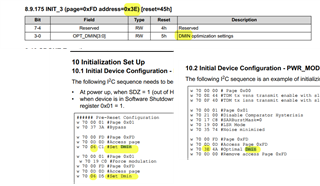
  • Well, we got a 44.1/16bit stereo wav file to play.  We then went bac to the original audio and amplified it (without clipping) and then it stopped playing as soon as it had any volume.  In looking for the reason, I ran across something set many times in the example code of "DMIN" but I cannot find any documented understanding of what that is, why the examples used both address 0x06 and 0x3E, and what all of the magic numbers that are set in the documentation mean and do.

  • Hi Tony, I checked the registers and found some interrupts and some settings that do not seem correct

    INT_LTCH0 - TDM clock error
    INT_LTCH4 - TDM clock error type = Invalid SBCLK ratio or sampling rate, TDM clock error type = Sampling rate changed on the fly

    Channel-1 Book0_Page0 0x08 TDM Configuration0 0x38 -> set to 0x28 enabled clock auto detection, also typically the frame will start on the falling edge of the Frame clock, but it may be OK dependent on the hosts settings
    Channel-1 Book0_Page0 0x09 TDM Configuration1 0x02 -> left justify 1bcclk offset
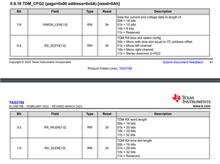
    Channel-1 Book0_Page0 0x0A TDM Configuration2 0x12 -> set to 0x10, set 16 bit slots and words to match the bus settings
    Channel-1 Book0_Page0 0x0C TDM Configuration Reg3 0x00 -> set to 0x10, settings are conflicting here

    Please give these a try. these settings are assuming that you have 32 Bclk/Frame and there is stereo data of 16 bits each. please let me know if that is not correct

    and regarding the DMIN, this is a setting on our test page that is related to the Linear LSR modulation used by our class-D. I believe this setting is related to the dither on the output. you can see the value referenced in our patent https://www.freepatentsonline.com/20200358431.pdf

    otherwise I cant share more about the testpage

    regards,
    Arthur

  • Thank you Arthur!  I think that helped, but I also tripped across another problem I was having that was sabotaging the sound data.  I was referencing this site, WAV - Waveform Audio File Format, to determine where the data started.  What was not obvious to me from that site was that WAV files also have a footer with context data and I was not trimming that data off the end of the file as well before grabbing the binary data (which also needs to be converted to big endian).  So with these settings and trimming the "footer" of the WAV file data as well as the "header," it worked quite well!  

    Kind regards,

    Tony

  • Hi Tony,

    Sounds like it is working now, let me know if you need further support.

    Regards,

    Arthur

  • Arthur,

    I thought I was home free, until I tried my second test sound file and it fails to play the whole thing.  The sound file is slightly larger so I tried 3 separate times to convert the sound file to binary using different amounts of shortening the tail end of the file as well as both slightly amplified and not amplified and in all cases, when played it sounds like it stops playing that sound data’s roughly second half of its stream. 

    As I have just enough memory currently to hold both sounds in memory, I tried playing the problem sound first and then my older test sound in case the problem sound was shutting off the amplifier, but it does not and the second older sound plays just fine.

    That being said, as I had not realized before I had to trim the ending of the wav file, I am still wondering if my conversion process from mp3 to WAV to Big Endian data is correct.  I have included my test sounds that start at the Audacity project file level and then through al the stages of conversion process.  I also have a word document (with two embedded videos) of the details on how I converted called “Brute Force Creation of the Sound Data.docx”.  I also have two very short video captures first me playing the second sound file through PPC3 control and then me playing the Second sound file and then the first sound file with 100ms break in between so you can hear how distorted and short it is when played through my external control.

    Finally, I added the PPC3 captures of the registers from both my setup and then from PPC3 setup.  Both seem to show the

    Book0_Page0

    0x51

    Latched Interrupt Readback 4

    0x06


    value.  Interestingly, regarding INT_LTCH4 bit 1, I was wondering if the reset was really 1 or of the description might be backward as the default reset is the error state if I am reading this correctly.


    test data and process.zip

  • Hi Tony, 

    that does look like a datasheet error, I will check with the datasheet owner. for your debug I think its safe to assume that 0= not detected for both, 

    It sounds like your issue may be more system level than an issue with the I2S signals or the TAS2780 settings.

    When you are playing the second not-working sound, when the audio stops what is happening on the I2S bus? do you see the clocks or data stop?

    Also, when you are not playing audio does your host stop the I2S clocks? (FSYNC/SBCLK) this could be the cause for the interrupts

    Regards,
    Arthur 

  • Arthur,

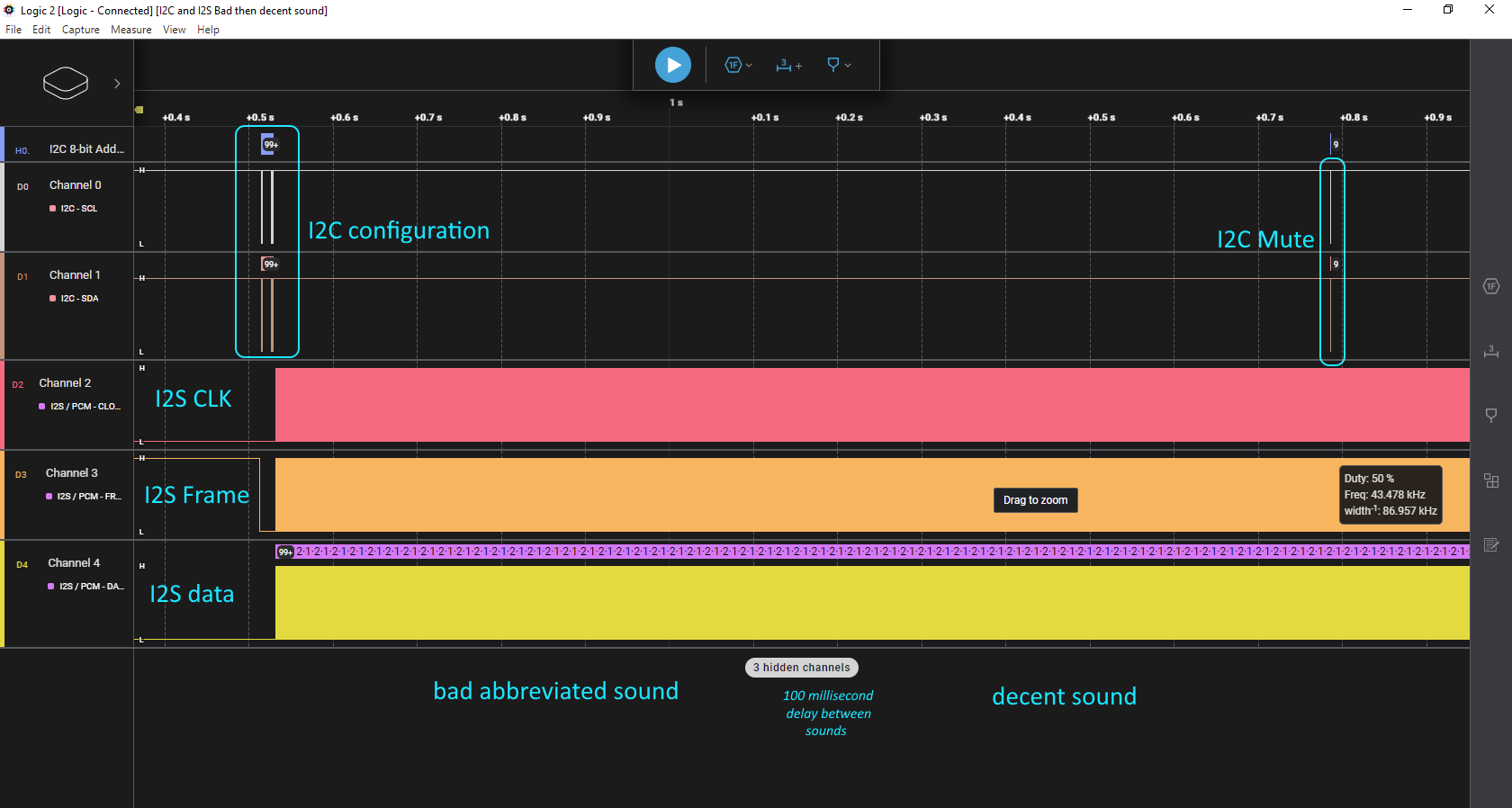
    When you are playing the second not-working sound, when the audio stops what is happening on the I2S bus? do you see the clocks or data stop?”   It appears that the data and clocks keep going.  At the end of playing the both sound, you can see from the capture that I send mute (0x99) to address 0x02 and then setting the digital volume to 0xC9 at address 0x1A which should be mute.  Al the while, the clocks do not stop.


    This full capture is uploaded here too as a Logic 2 capture.  Zoomed out, you can see the I2C setup, then very shortly after, the I2S trouble sound immediately followed by the OK sound are played immediately followed by the I2C mute command.  If you do not have Logic 2 from Saleae, it can be downloaded from https://www.saleae.com/downloads/ to see all the signals (zoom in/out) as desired.
    I2C and I2S Bad then decent sound.zip

    Also, did you get a chance to see the conversion process to extract the audio data from the original sound files in the previously uploaded document “Brute Force Creation of the Sound Data.docx” and does this track with what you know?

    Thank you,

    Tony

  • Hi Tony, 

    thanks for this I will review it, can you also provide your device initialization script (I2C script)?

    Regards,
    Arthur

  • As I am configuring from my external device, I spent a little time trying to format it and providing clarity.  So, the zip file has the actual registers and data I am sending over to change the default status.  From a very high level, the process is:

    1) I2C send the first chunk of configuration data called "I2C_power_ALT_1a"

    2) Pause 10ms then I2C send the second chunk of configuration data called "I2C_power_ALT_1b"

    3) Pause 2ms and send 2 sound data streams with 100ms pause between them

    4) Send mute register settings

    At this point, I then moved the J24 jumper to 'USB', connected PPC3 and pulled the Register Map to confirm what was sent (also included in this zip file) which seems to match although two registers for digital volume and AMP level do reflect the "mute" sent after playing the sounds.

    Configuration data.zip

    Thank you!

    Tony

  • Hi Tony, 

    Checking the Salae capture nothing stands out as incorrect.

    however when reviewing your initialization I see a few things that may be wrong.

    - the device power up command "Active without mute" should be the last command sent. configure the device then power up.

    - you are setting the slot and word length both to 16, however you have 32 BCLK/Frame. the correct setting should be slot length to 32 and word length to 16

    Regards,
    Arthur

  • Thank you Arthur!  I moved the power up to be after everything in configuration, even with small delay before sending that and it does sound decent but not so on the problem sound data.  Also, the slot length issue was my document's problem where I had the comment incorrect but the actual code correct. 

    I appreciate this code review in that it seems to bolster my growing suspicion that my process for creating the raw sound data that I sent back in this forum thread in a zip file on Jan 22 called Brute Force Creation of the Sound Data.docx.  Given that supposition that the process is not fully correct, I am looking for a way to convert MP3 (or even OGG) files to the needed raw PCM data to send to your amp chip to confirm my process is lacking.  What I have been pointed towards so far is trial proprietary demo libraries lacking full translation support, so I am looking elsewhere.  I suspect, if I can consistently send properly transformed raw PCM data, I will be actually fully in the clear!!

    Tony

  • Hi Tony, 

    I'm not able to comment on your audio file creation, it is a bit outside the scope of what we do here. however it seems reasonable, generate the audio file, remove the header information used by the streaming software, then load the data into your code. 

    Do you have a way to plot the data and view the waveform after you have created it? it may help see if there is an obvious issue.

    Regards,
    Arthur

  • Hi Arthur,

    The PCM data is now flowing properly and now it is obvious the volume is nowhere close to what I was getting when the XMOS chip was in play.  Here are the three things I did to maximize the volume:

    1. The original sound file was amplified to max amplification without clipping in Audacity before its export to WAV.
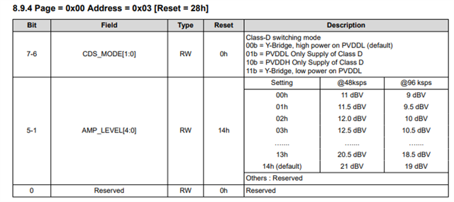
    2. Set page 0x00 address 0x03 to the value 0x28 (0010 1000 b) to set AMP_LEVEL to 0x14
    3. Set page 0x00 address 0x1A to the value 0x00 to set DVC_LVL to:  00h = 0 dB

    The sound data I captured on the scope does match the PCM data I am sending.  We even thought it might e a bit-shift issue so we tried to play with page 0x00 address 0x09 to play with the RX_OFFSET which sounded good but quiet at 1, nasty at 0, louder at 2 but starting to sound distorted, and more distortion and a tiny bit louder at 3.

    Do you know what I am missing in the configuration so it gets to the much louder setting I was hearing with the XMOS chip with sound from the PC through the usb?  

    Thank you,

    Tony

  • Respond in one moment

  • Yes, thank you Arthur for any additional hints or direction you may have for maximizing volume.

    Tony

  • Hi Tony,

    Appoligies, I would have also asked you to check the RX offset, as each bit offset will be a 6dB volume change. I once again checked your register configuration from earlier and the settings are in agreement with the recent scope shot.

    One thought, when you are adjusting the RX offset you will be moving the MSB closer to the start of the frame, and at some offset you will eventually drop the MSB completely. when this happens it should be an obvious distortion at the speaker.

    also, 21dBV gain will be 15.84 Vpeak or ~11.22Vrms at the output of the amplifier. if your supply voltage (PVDD) is less than 15.84V then there will be some clipping at the output.

    I am not sure how much test equipment you have but, it may be easier to debug if this is an offset issue by using a sine tone. 

    1) Generate something like 0dBFS 1kHz 

    2) disconnect the speaker because 0dBFS sine tone will almost certainly damage it

    3) make sure PVDD is >16V

    4) play 0dBFS 1kHz and measure the Vrms at the output. If the scale is correct then it should measure ~11.22Vrms. 

    You could also adjust RX_OFFSET in this test case and see if the MSB is being dropped or some other type of clipping is occuring. 

    Regards,
    Arthur

  • Hi Arthur,

    Regarding "if your supply voltage (PVDD) is less than 15.84V then there will be some clipping at the output", Kevin and I were wondering about our board design. As it is now, our supply is 12VDC. Do you think there are any adjustments we need to make to ensure compatibility with a 12VDC supply?

    Thank you,

    Tony

  • Hi Tony, 

    Sorry for the late reply. 

    the default channel gain will be 21dBV = 15.84Vpeak. i.e. full scale digital input will try to drive 15.84V on the output

    for a 12VDC supply you can lower the channel gain to match this supply, something like 18.5dBV will be 11.85Vpeak

    Regards,
    Arthur