This thread has been locked.

If you have a related question, please click the "Ask a related question" button in the top right corner. The newly created question will be automatically linked to this question.

TPA3255: TPA3255 - IC Power Pins Damage

Part Number: TPA3255


Hello team,

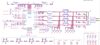
We are using TPA3255 IC for 240W application.

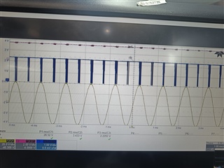
Setup Info - Testing with 4-ohm resistive load.

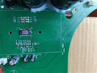
Board 1 - Board Impedance was normal and test was conducted for 2 days. When the DUT was powered on next day, we observed that power pins of IC got damaged, and the pad is also damaged. Image attached for reference. Image attached for reference.

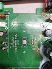
Board 2 - Board Impedance was normal and test was conducted for 2 days. After a gap of 2 days, DUT was turned on, and was behaving normally for 10-15 mins. Later, intermittent output was observed and finally IC was damaged, and smoke was emitted from the same. However, this time only the power pins were damaged, and pad was intact. Image attached for reference.

Thermal Test was done prior to the damage, and the stable temperature with heat sink was ~75-85 deg C.

Also, after the damage, it was observed that output impedance was 0.4, and power supply rail of GVDD, VDD and DVDD was also showing 1.6-ohm impedance.

I kindly request you to help us understand on the possible root cause for the same, as delivery is critical and only 1 working sample is available.

  • Hello,

    • Can you provide the schematic and layout for your design, do you have the voltage/current rating for the bootstrap caps, power supply caps, and output filters
    • What are you using for the heatsink and thermal compound in this system
    • Can you provide specific technical detail on what are you doing on the test, what's the input signal you are using, what's the output, do you have waveforms of what what being done during the intermittent behavior? Did you observe any fault reported before failure?
    • Have you run this on multiple boards, if you replace the IC and run the same test do you see the same behavior?

    best regards,
    Luis

  • Hello Luis,

    I cannot share the schematics and layout in this forum. Please let me know if there is any email ID over which I can send the screenshot of the same.

    • Schematic screenshot of the amplifier section is given below:

      The voltage ratings of Caps are provided in the image. If more details are needed, please do let me know.


    • Heat Sink - We have a new heat sink which is similar to EVM (TPA3255EVM User's Guide (ti.com)).  We have used Anabond Thermal Paste.
    • Input Signal - Signal with Sensitivity of 200mV, 1kHz sine signal. We were capturing the various Audio Parameters such as Frequency Response, SNR, THD, Voltage level etc. The input signal will be amplified at various stages, input to Class D Amplifier is 2.6V, and the final expected RMS output from Class D Amplifier is 32V. Before the IC went bad, we observed that output was very low for few trials (<1V). After power-off and power-on, the output was as expected, and again low output was observed. Finally, the IC was damaged when input signal was provided in case of Board 2. In case of Board 1, normal power-on damaged the IC and generated sparks.
    • We have 3 samples, out of which 1 sample failed along with the pads, which couldn't be replaced. Other sample, we replaced the IC and testing was started with heat sink provided with EVM. After 30 mins of test, the output dropped to 8V RMS from 32V (Temp of heat sink observed in thermal camera ~ 80 deg C). We switched off, and allowed it to cool, but even after a fresh power on, the output is 8V and is not as per the expectations. Even after allowing the device to cool down for more than an hour, when powered on, output reached 15V and dropped to 7V.
  • Hello Luis,

    We have changed multiple ICs (3-4), and none of the ICs are withstanding beyond few hours of full load testing(240W).

    We have monitored the fault and clip signals in a good device currently on board, and it was observed that with ~ half volume, Clip started going low. Waveform attached for reference.

    I kindly request you to suggest us on what could be the possible cause for failures.

    1. If temperature is a concern, we have tried with Heat Sink provided with EVM, and yet the IC did not function completely for few hours also.

    2. If temperature is a concern, the device should shut down and should not work until a new power on. Why are the devices getting damaged?

    3. If above two points are not true, what other points could be a cause of failure?

    I kindly request you to help us as timeline is very critical, and we need your support to resolve the issue. 

  • Hello Mayur,

    You can send me an email at luisvf@ti.com to send your layout for further review. What's your PVDD? Also are you able to test a direct path from your power supply to the PVDD input of the device, I see there is a inductor between your supply and the PVDD of the amp. So either testing with a higher current inductor or direct connection to PVDD would be useful. Could you also provide an inductance vs current plot for the component you are using on the PVDD side and the output side

    One thing looking when looking at your layout would be the ground return path from the output to the device, if this is poorly done could lead to an overcurrent condition that may cause damage.

    Some general guidance we have provided in the past: TPA32xx-Grounding-Notes.pptx 

    Additionally decoupling capacitance being close to the power pins being critical. What is being used as the power supply in your tests as, to clarify the fault of this device isn't triggered at all during the test just OTW?

    best regards,
    Luis Fernandes de Pina