- Ask a related questionWhat is a related question?A related question is a question created from another question. When the related question is created, it will be automatically linked to the original question.
This thread has been locked.
If you have a related question, please click the "Ask a related question" button in the top right corner. The newly created question will be automatically linked to this question.
Tool/software:
I am working on a stereo design using two TAS2781 chips. Not battery powered, but rather working from a +24V high voltage rail. The data sheet is a little sparse on stereo configuration information. Is there a stereo reference design or any other stereo configuration material that might help?
James
Hi James,
when we are doing two devices in a stereo configuration there are two items to consider.
-TAS2781 supports the external Class-H(Multi level) boost controller. in a stereo configuration they can be connected together as described in this app note https://www.ti.com/lit/an/sloa326/sloa326.pdf?
-Since this does not apply the other item to consider is we have a stereo gain balancing feature. which shares gain information between two devices to help maintain the stereo image under hard audio playback. this is described in section 8.4.2.11 of the datasheet. In the schamtic all is required is pin 6 of two TAS2781 devices is to be shorted together.
Regards,
Arthur
Hi Arthur,
Thanks for that. I was aware of the first point, and suspected as such for your second point. I have one other question. I understand that the pair of chips can share a DATA IN line and can also share the same DATA OUT line. In both cases they can be configured to individual slots within the stereo pair, and in the case of the DATA OUT line they will go Hi-Z when the other chip is sending. Please confirm if my understanding is correct. Here is the question: in the case of IV monitoring on the DATA OUT line, are the I and V sent as stereo left and right, or can they be? I don't see a way to configure this. Of course this also relates to how the two chips can share one DATA OUT line and both send IV data. In my design, the processor can accept two DATA OUT lines, one from each chip, but I wonder if that is even needed. Clarification would be appreciated.
James
Hi James,
In both cases they can be configured to individual slots within the stereo pair, and in the case of the DATA OUT line they will go Hi-Z when the other chip is sending
this is correct.
in the case of IV monitoring on the DATA OUT line, are the I and V sent as stereo left and right, or can they be? I don't see a way to configure this. Of course this also relates to how the two chips can share one DATA OUT line and both send IV data. In my design, the processor can accept two DATA OUT lines, one from each chip, but I wonder if that is even needed. Clarification would be appreciated.
James
both shared DATA OUT and individual DATA OUT connections can be used. even if DATA IN is shared between the devices. the I and V data are transmitted by default as 16 bits, and the data slots coming out of TAS2781 are 8 bits. meaning both I and V will take two slots. for example device "A" can be configured to transmit 'I' in slot '0' and will extend through slot '1', and 'V' can be configured for slot '2' and will extend through slot 3. and device "B" can use slots '4' and '6' in the same manner.
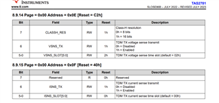
to enable the IV transmit use registers 0x0E and 0x0F. an example configuration is below
"w(write) 70(Device address) 0e(register address) 40 (register data)"
w 70 0e 40 #enable device with address 0x70 to transmit 16 bit voltage data in slot 0.
w 70 0f 42 #enable device with address 0x70 to transmit 16 bit current data in slot 2.
w 72 0e 44 #enable device with address 0x72 to transmit 16 bit voltage data in slot 4.
w 72 0f 46 #enable device with address 0x72 to transmit 16 bit current data in slot 6.

Regards,
Arthur
One final question (I hope): The data sheet has no mention of the need for a heat sink, so I assume a heat sink would not be required to meet spec. Please confirm. Would it help in any way? I'm at the point in the layout where I need to know whether to leave access for it or not.
Thanks
No heat sink is required and there is no exposed thermal pad on the device so it would not efficiently conduct heat if it was added.
Arthur, I have a few more questions and as always appreciate your replies.
1. Is it possible to parallel two chips to drive more power into a single driver? This assumes they are configured the same, and driven from the same I2S signal and clock.
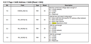
2. This is probably related to using the on board processing. Is it possible to blend or mix L and R channels on a single chip output?
3. It is not clear to me how to engage the on board processing filters, if NOT using characterization for the driver. I am so far operating out of ROM mode. How would I configure a single highpass or lowpass for the goal of using it as part of a two channel crossover? Is this even possible?
James
Hi James
1.) This is not an officially supported operating mode, if we have device A and device B outputs shorted together. if there is a moment device A switches to PVDDH and Device B switches to Ground then there would be an over current error, this risks damage, and one device would turn off. The two devices Class-D switching would need to be synchronized to the ps timescale. Out of curiosity i tested this on an EVM and admittedly it did seem to work for short durations at low output level, but quickly one of the channels would experience and error and shut down.
We do support such a parallel 'PBTL" configuration on stereo amplifiers(Such as TAS5825M). in those devices however the internal circuitry can be perfectly synced and this issue isnt present.
Have you considered TAS5825M or similar parts? TAS5825 will be able to deliver much higher current, with an exposed thermal pad., and it also has the same DSP capabilities as TAS2781, filtering EQ, compressors etc.
2.) this can be selected in page 0 register 0x0A

3.) enabling filtering will require the use of the tuning mode. the current public PPC3 release does require the driver characterization to be entered, because to enable the other filtering and features the smart amp protection+ Driver characterization must be entered as well, otherwise the output from the amp will be very low. We have a pending public release that will allow the characterization to be bypassed and still allow the other filtering and features to be used. I will check with the PPC3 team of the target release date. if it is not very soon i can provide a beta version to you which can be used in the meantime
Regards,
Arthur
Thanks Arthur. From what I can tell:
Am I getting this correct?
Hi James,
Yes your understanding is correct.
May i ask how much current/power is needed in your case?
Also I have heard from the PPC3 team that they are targeting the end of the week for the public release of the new PPC3 version.
Regards,
Arthur
Arthur, I'm looking at multiple designs. For the first one, I'm going to stick with two independent TAS2781 at ~25W each, into 4ohms This is perfect for this design as there is no real need for PBTL. It has the Class H and I/V that I need.
In the next design, there will be more channels. I'd like the ability to do PBTL with the same power level as TAS5825. So option A would be to use two TAS5825M. Class H will not be necessary on this board, but I really would like to have I/V output. Is there some other device I should consider?
Hi James,
TAS2781/ TAS2780 are our highest current options with IV-sense.
Have you investigated making some external IV sense circuitry with an instrumentation amplifier + Sense Resistor + ADC?
Do you need the IV sense for speaker protection or some other use case?
Regards,
Arthur
That's helpful to know. We have already built an I/V logger in an external rack mount enclosure. It works well. Our need for the I/V output is exploratory at this point, and we may indeed use it for speaker protection down the line. I look forward to the new release of PPC3.
Thanks for your help.
Hi James,
OK, Understand, PPC3 team is based in India. I Will touch base with them tonight, otherwise I will provide it over email tomorrow.
Regards,
Arthur
Hi James,
I shared the beta version with you as the public release still has some time before it is available. Please let me know if you have any questions