This thread has been locked.
If you have a related question, please click the "Ask a related question" button in the top right corner. The newly created question will be automatically linked to this question.
Tool/software:
Hello:
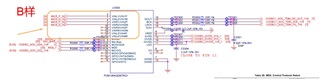
At present, the mic interface channel has been adjusted in sample B. Sample B is only connected to two channels of MIC. The DOUT of PCM1864 in sample B has no output (level 0). TDM CLK and FS signals are input normally. Please help confirm which registers need to be modified? Thanks!!!
The software register configuration is as follows:
i2cdbgr -D /dev/i2c1 -s 0x4a -w -b 2 -o 0x01 -x 0x20
i2cdbgr -D /dev/i2c1 -s 0x4a -w -b 2 -o 0x02 -x 0x20
i2cdbgr -D /dev/i2c1 -s 0x4a -w -b 2 -o 0x03 -x 0x20
i2cdbgr -D /dev/i2c1 -s 0x4a -w -b 2 -o 0x04 -x 0x20
i2cdbgr -D /dev/i2c1 -s 0x4a -w -b 2 -o 0x05 -x 0xe7
i2cdbgr -D /dev/i2c1 -s 0x4a -w -b 2 -o 0x06 -x 0x41
i2cdbgr -D /dev/i2c1 -s 0x4a -w -b 2 -o 0x07 -x 0x41
i2cdbgr -D /dev/i2c1 -s 0x4a -w -b 2 -o 0x08 -x 0x41
i2cdbgr -D /dev/i2c1 -s 0x4a -w -b 2 -o 0x09 -x 0x41
i2cdbgr -D /dev/i2c1 -s 0x4a -w -b 2 -o 0x0b -x 0x03
i2cdbgr -D /dev/i2c1 -s 0x4a -w -b 2 -o 0x0c -x 0x00
i2cdbgr -D /dev/i2c1 -s 0x4a -w -b 2 -o 0x71 -x 0x80
i2cdbgr -D /dev/i2c1 -s 0x4a -w -b 2 -o 0x73 -x 0x03
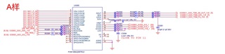
Sample A
Sample B
Hi Jimmy,
Apologies for the delay, I will loop in additional ADC expert for support
Hi Jimmy,
A couple of queries:
1) Based on the configurations above, the device is operating at 48kHz with TDM (which requires 256 BCK per frame), is this correct?
2) Can you share the readback values of the device status and interrupt registers in this condition?
Thanks and Regards,
Lakshmi Narasimhan
The readback values below, please help to check.
Hi,
Couple of observations based on the register readback values:
1) The registers 0x1-0x4 are begin written to 0x20, but readback is showing 0x0. Similarly, the Registers 0x6-0x9 are being written to 0x41, readback still shows 0x0.
2) The register 0x28 is reading 0x3, indicating that PLL is not locked. Additionally, register 0x72 is reading 0x0 indicating device is in power-down status. Register 0x74 is reading 0x77, indicating that the BCK/SCK ratios are invalid, or LRCK halt.
3) The register 0x73 is a read-only register, the above configuration is trying to write it to 0x03.
4) Register 0x75 is reading 0x57, indicating clock halt and clock errors.
Can you share the sampling rate and BCLK/SCK frequencies that is being provided to the device?
Thanks and Regards,
Lakshmi Narasimhan
Hi,
The device BCLK frequencie is 12.288MHz(f sampling=48Khz, 8 channel, 32bit).
The register 0x72 is writing failure(
), what's the cause?
The AVDD, DVDD and IOVDD is normal.
Hi,
Are we trying to write into the register 0x72 into the host.
The register 0x72 is a read-only register, it gives out the current status of the device operation?
The register 0x72 reading back 0x0 is indicating that device is in shut-down state, and based on the 0x75 readback in previous comment, it is indicating clock error flag. The register 0x74 is also reading 0x77, indicating invalid BCK ratio/SCK ratio.
Thanks and Regards,
Lakshmi Narasimhan
Hi,
This case can be closed.
The main reason is that the software ACDB audio configuration file push don't effect.
Hi,
Thank you for the confirmation, closing this thread now.
Thanks and Regards,
Lakshmi Narasimhan