This thread has been locked.

If you have a related question, please click the "Ask a related question" button in the top right corner. The newly created question will be automatically linked to this question.

TLV320AIC3120EVM-U: Unable to get the required log from TLV320AIC3120 EVM using codec control software

Part Number: TLV320AIC3120EVM-U
Other Parts Discussed in Thread: TLV320AIC3120

Tool/software:

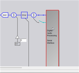
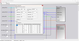
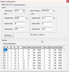
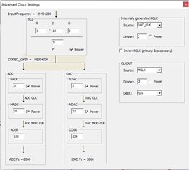
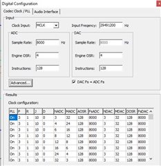
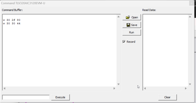
I am working with TLV320AIC3120 EVM. I am using codec control software to configure the codec, so as to test the ADC and DAC. I have taken the default log which comes once I connect the EVM to my system. I made the same log to be executed in the EVM. I have connected mic and speaker in the two jacks provided and have tested and verified that mic and speaker is working. The default sampling frequency is 44.1 KHz. Now, I want to change the sampling frequency to 8 KHz. I have tried changing it thorugh codec control software, so as to get automatic log accordingly. But I could'nt do it. Is there any way by which I can do it? Finally, I want to interface the board with the PSOC6 microcontroller eval board, so that I can program the codec through I2C registers. My requirement is 29.4912 MHz master clock from an external oscillator and 8 KHz sampling frequency. I want the corresponding log for this, so as to program codec with microcontroller.

  • Hi Aarathi,

    Changing the sample rate of the EVM is not straightforward because it was designed for typical PC use. Codec control cannot change it because the clocks are coming from the TAS1020B.

    You can follow these instructions to change the firmware on the TAS1020B to 8kHz: https://e2e.ti.com/support/audio-group/audio/f/audio-forum/773576/faq-tlv320aic-codecs-and-adcs-how-to-restart-revive-a-usb-audio-evm

    If you are using external clocks (like from the microcontroller) you need to first remove the connection from the TAS1020B so that there is no clock contention. Then in codec control you can go to "Serial Interface" and then click "Internal Clock Gen Module". This will help you create the necessary PLL values to get the right settings.

    Best regards,
    Jeff McPherson

  • I have tried changing the sampling frequency using the "Serial Interface", as you have mentioned, and I am able to change it. I am attaching the clock division parameter settings that I got from the codec control software. But I didn't understand how to disconnect TAS1020B. And also, how can I save these settings, so as to get the log automatically generated according to these settings. After setting this also, the USB Fs shown in the codec control software is 44100 Hz. I want this to get changed to 8000 Hz and get the log accordingly. Is there any way to get that? Also, in my case, MCLK is not given from the microcontroller. It is given from an external oscillator. BCLK and WCLK are given from microcontroller.  

  • Hi Aarathi,

    If TAS1020B is connected to codec I2S interface, then changing the settings in the codec control will have no effect. Codec Control GUI has no control over TAS1020B, which is I2S master. Your clock tree seems valid but it doesn't matter, because TAS1020B will continue to give 44.1kHz Fsync and 256*fs BCLK. It is not convenient to do so, but you can try to remove the test points on the EVM or cut the traces and replace with 0 ohm resistors. to interface with external controller. If you want to change the sample rate coming over USB you have to change the firmware in the TAS1020B which is described in the link I gave above. This EVM was unfortunately not designed with flexibility in mind, it is more of a "plug and play" only type EVM.

    You can open the command window, and check "record" which will capture all I2C writes that are done in the GUI. I assume this is the log you are looking for.

    Finally, it is not recommended to provide MCLK from one source and BCLK/FSYNC from another. MCLK and BCLK/FSYNC must maintain a phase relationship, and so drift in the oscillator can destabilize the I2S bus. When using an external oscillator it is recommended to make BCLK and FSYNC outputs from the codec (master/controller mode). See the app note below.

    https://www.ti.com/lit/an/slaa469a/slaa469a.pdf?ts=1730888517873

    Best regards,
    Jeff McPherson

  • Okay. I understood that I cannot change the sampling frequency of the EVM without changing the firmware of TAS1020B. Now, I want to get the hex values to be written in to the registers for the corresponding configuration, where the sampling frequency is 8 KHz and master clock is 29.4912 MHz. But, when I checked in the register inspector, the values are not getting updated. Is there any provision to get the hex values corresponding to our configuration? I saw that whenever I am clicking the clock configuration parameters which I got with my configuration, I am getting the corresponding log in the command buffer? Can I use that log for I2C clock configuration from the microcontroller?

    Also, for my requirement, in the Tx chain of the system, ADC should work, and DAC should be off. In the Rx chain, reverse should happen. Can I know the sequence in the configuration for this to happen? Irrespective of Tx and Rx, in the initial stage itself all the clock configurations and MIC BIAS should be done, right?

  • Hi Aarathi,

    Click "refresh" in the register inspector in case the reg map isn't updating, and make sure you are looking at the right page.

    However yes, you can use the writes generated in the command buffer to configure the codec from your microcontroller.

    ADC and DAC paths are by default not connected to each other, so there is no required sequence in order for your configuration to happen. In Tx to Rx switch, you can power down ADC and then power up DAC or vice versa. Same for Rx to Tx switch. Anything not unique to those paths (I2S, Clocks, MICBIAS, gain settings, etc) should be done first.

    Best regards,
    Jeff McPherson