This thread has been locked.

If you have a related question, please click the "Ask a related question" button in the top right corner. The newly created question will be automatically linked to this question.

DRV135: Difference in the P and N output values of the DRV135

Part Number: DRV135


Tool/software:

Hi Team,

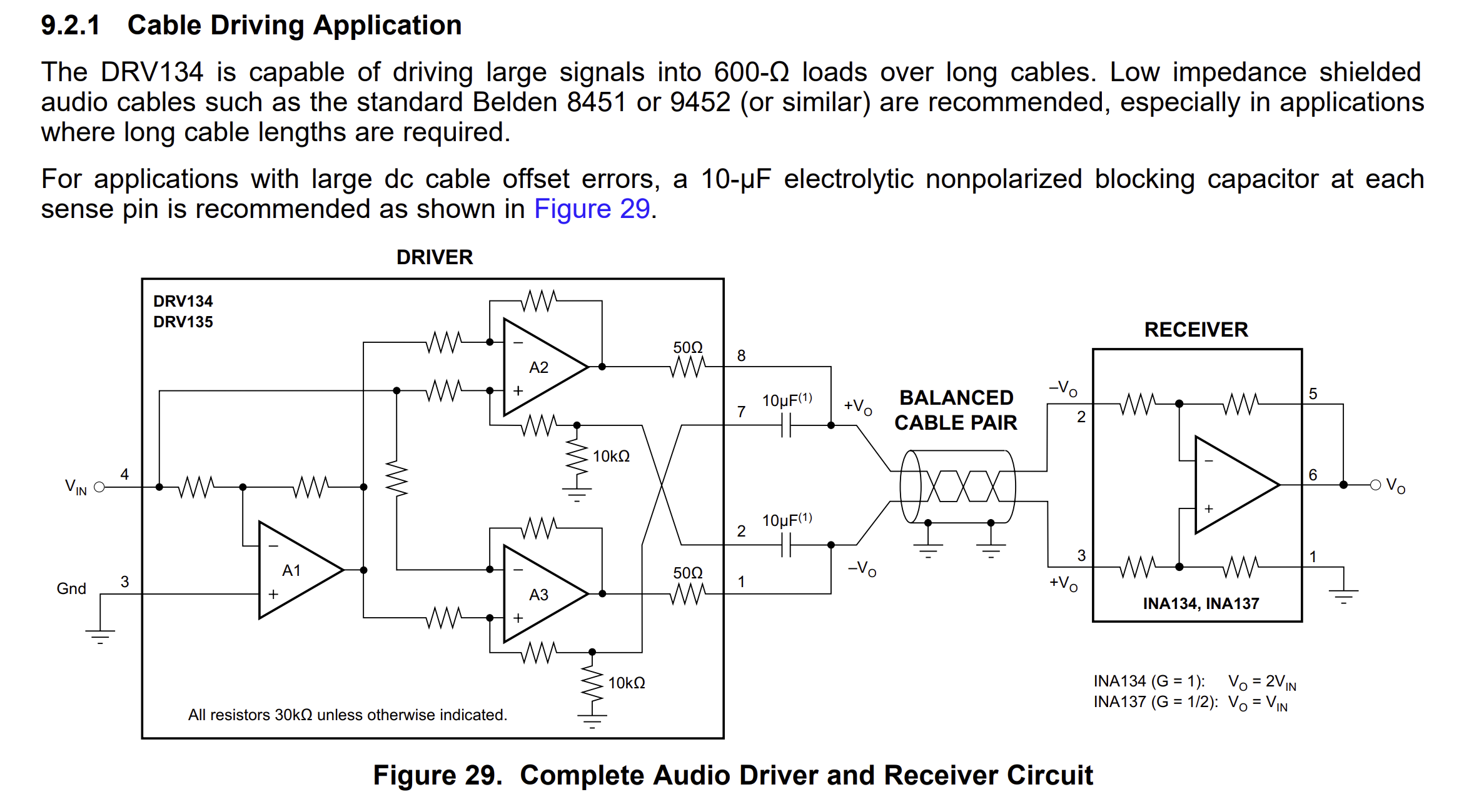
I have used DRV135 to convert single-ended to differential signal.

There is a noticeable difference between the P and N output values of the DRV135. Can anyone help determine the exact cause?

Below are the observations:
Vin: 3V

Across P & N = 6.45V
P v/s GND = 3.25V 
N v/s GND = -3.18V

Vocm = 250mV(max) // As per datasheet

Vodm = 10mV(max) // As per datasheet

  • Hello, 

    I have simulated 3 scenarios below. I used DC blocking caps on the sense pins to DC block any current and offset errors. This scenario is our reference design. I also ran the simulation without these caps and the last with no caps and no load. you can see the current flowing into the sense pins is creating the error. This scenario replicates your setup. I have attached my simulation at the bottom of this post. 

    Below we recommend using the DC blocking caps for applications with large offset errors. You can see any current going through the sense lines will create an offset voltage back to the internal non-inverting terminal of the output amplifiers. We have several circuits in the PDS without the DC blocking caps but note that there is a resistive load connected on the outputs similar to scenario 2 above. Can you try using a resistive load on the outputs to see if the errors are reduced?

    5734.DRV135.TSC

    Best Regards, 

    Chris Featherstone