Because of the holidays, TI E2E™ design support forum responses will be delayed from Dec. 25 through Jan. 2. Thank you for your patience.

PCM6140-Q1: Noise & A1-A4 Pins

Part Number: PCM6140-Q1
Other Parts Discussed in Thread: TLV320ADC6140

Tool/software:

I am at the point where I've moved the design mentioned in my previous post (which should be linked to this thread) from a breadboard to a perma proto board. And I've actually built 3 copies. All 3 copies are functional. But I am getting some audible noise in my recordings for which I'm trying to diagnose the cause. I would upload a 10 second sample of audio, but that doesn't appear to be possible on the forum here. The noise is a cyclical "whirring" sound that appears to increase with higher gain settings for the codec's PGA. If there is a way to provide an audio sample let me know...

What occurred to me, however, and the question for which I'm specifically looking to find an answer, is that in order to facilitate hand-soldered construction of my prototypes, I am utilizing a QFN-24 to DIP-28 adapter from Proto Advantage. Specifically one of these:

https://www.proto-advantage.com/store/product_info.php?products_id=3100014

What I realized is that the PCB to which they have mounted the PCM6140-Q1 parts, however, does not have pads at the A1, A2, A3, and A4 pin positions on the PCM6140-Q1. Consequently instead of being connected to ground, these pins are simply floating. How much of a potential contributor is this to noise levels? Is it a possible cause of the noise I am hearing?

I know TI also has the non-automotive TLV320ADC6140 part which does not have these additional ground pins. I'm debating whether I should consider ordering some of these mounted on the same adapter from Proto Advantage to determine if the lack of grounding on the A1-A4 pins could be the cause of some of the noise. Does this seem like a worthwhile endeavor?

Thank you in advance for any advice you can provide on this somewhat nebulous issue.

-- William

  • Hi Will,

    The corner pins on this device were likely added by design for mechanical stability as opposed to electrical. This is to substitute a package change such as wettable flank for example and should not induce any noise in the system if left floating.

    Do you want to share your schematic? We can troubleshoot here

  • Hi Daveon,

    Thank you for checking on this for me. You've saved me the time of needlessly pursuing replacement of the PCM6140-Q1 with the TLV320ADC6140.

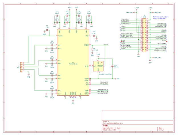
    The design is very similar to the one I shared on the linked original question when I was using a breadboard. But here is an updated schematic that more accurately reflects the reality of what I have constructed on the perma-proto board:

    It is based, of course, on the reference design in the PCM6140-Q1 data sheet. Note, however, that I'm using larger 22 uF capacitors along with the 2.5 kOhm impedance setting for a ~2.9 Hz high-pass filter on the inputs. This is because we are using the ICS-40300 from TDK InvenSense which has an extended low frequency response down to 6 Hz and we are hoping to potentially pick up potential infrasound.

    I've added a 24.576 MHz oscillator to allow for the choice of having either the codec or the RPi providing the audio bus clock. All of my current test recordings, however, have been made with the RPi providing the clock and the codec locking on to that.

    Here are some photos of one of my assembled prototypes:

    Our goal with the prototypes is to be able to record samples of the target sounds for ML training purposes. Eventually, if the ML training goes well, moving to a detection device that puts all of the analog and ADC components on a PCB with a socket attaching to some form of RPi (depending on the compute needed for the ML). Possibly one of the RPi compute boards.

    Based on your feedback above regarding the A1-A4 pins, my current thinking is that the noise is likely coming from my inability to well-separate the analog and digital supplies/lines on this small perma-proto board. In particular, due to space constraints, the clock line from the oscillator is running under the gray IN[1-4]P signal lines.

    I'm thinking my next step may be to try using a larger perma-proto board where I can better separate those analog and digital lines, supply, and ground. Adding a low-noise, LDO, regulator to generate a +3.3V supply for the analog side of the board from the RPi's +5V supply. And using the existing +3.3V supply from the RPi only for the digital side of the codec.

    Does that seem a reasonable approach? And, if so, would you have a recommendation of a low-noise, LDO, regulator for this purpose? Preferably one that is available both in TO-220 (or similar) format for easy handy assembly of prototypes and surface-mount format for the (eventual) PCB. And, of course, a TI part!

    Oh... BTW... I earned a BSEE in the early 90's and, until recently, have worked almost exclusively on the software side of things. So my EE knowledge is a touch rusty. And, even when it was fresh, I specialized in semiconductor physics and VLSI design. Not audio engineering. So if I'm doing something stupid above please feel free to point that out. :-)

    I've got a 1.9 MB, 10 second, WAV file containing a voice recording with the noise I'm getting. Let me know if there is a way I can provide that to you if that would help.

    Thanks again for all your assistance!

    -- William

  • Hi William,

    Thanks for the detailed response! The schematic looks okay and shouldn't cause the 'whirring' sound you described. My concern is now with the GND pins so I am going to double check with our design engineer and confirm if A1-A4 are connected to the thermal pad on the lead frame. If they are not, then I do suggest transitioning over the commercial part, TLV320ADC6140.

    Please ensure the thermal pad is soldered to the PCB and a good GND connection is established. I will update the thread this week with feedback from design.

  • Hi Daveon,

    Thanks for the update. Yes. I actually double-checked with the Proto Advantage folks back in mid September that the thermal pad of the PCM6140-Q1, when mounted on their IPC0014 QFN-24 to DIP-28 adapter, has the thermal pad of the QFN-24 part attached to the 4 corner pins labeled "25" in my photo above. And I have all 4 of those corner pins connected to ground on my perma-proto boards. So the thermal pad should be well connected to ground. As is the AVSS (pin 4) of the PCM6140-Q1. But not the A1-A4 pins.

    Here are the two photos they (Proto Advantage) have showing the board:

    https://www.proto-advantage.com/store/images/PRODUCTS/IPC0014_2.JPG

    https://www.proto-advantage.com/store/images/PRODUCTS/IPC0014_3.JPG

    I'll look to hear back later in the week. Thanks!

    -- William

  • Hi Daveon,

    It seems like the Image/video/file insertion option *might* let me attach the WAV file with my 10 second sample. Attempting to do that with this post.

    -- William

  • Thanks, I've pinged design and will update the thread asap

  • Hi William,

    Our design team confirmed that the thermal pad is connected to pins A1-4 internally.

    To better troubleshoot noise issue, are you able to send a 1kHz sine tone into one channel (1Vrms full-scale when the input is single-ended), confirm what the IC is seeing after the capacitor using an oscilloscope, and record the output?

  • Hi Daveon,

    Thank you for your continued assistance with this issue. I've done as you've suggested and found some confusing results. I'm using a Diligent Analog Discovery 3 along with their WaveForms package for the following. First a photo of my test setup:

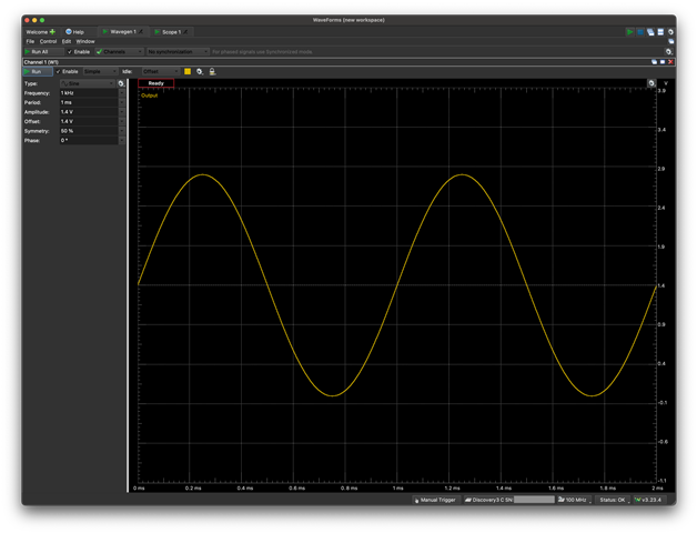
    I've got waveform generator 1 inserted into the single-ended input #1 connection on my terminal screw block. Oscilloscope connection 1+ is inserted into the open hole for IN1P immediately next to the socket. I.e. placed between the codec and the capacitor. Oscilloscope connection 1- is inserted into the open hole for IN1M immediately next to the socket. Again between the codec and the capacitor. I have the wave generator configured as follows:

    1 kHz sine wave varying +/- 1.4V with a DC offset of 1.4V. Which I believe is the ~1 Vrms signal you were looking for.

    On the software side of things I have:

    ADC_FSCALE = 0 (VREF = 2.75 V)

    AREG_SELECT = 1  (Use the on-chip regulator to generate AREG = 1.8V)

    INCAP_QCHG = 3  (Quick Charge Duration = 50 mS due to the 22 uF coupling caps)

    MBIAS_VAL = 6  (MICBIAS to AVDD = 3.3V)

    IN_CH1_EN = 1, all others zero

    CH1_DC = 0  (AC Coupled)

    CH1_DREEN = 0  (No DRE or AGC)

    CH1_DVOL = 201  (Digital Volume Control = 0 dB)

    CH1_GAIN = 0  (Channel Gain = 0 dB)

    CH1_IMP = 0  (Input Impedance = 2.5 kOhm)

    CH1_INSRC = 1  (Single-Ended Analog Input)

    CH1_INTYP = 0  (Microphone Input)

    GPIO_CFG = 0  (Disable GPIO1)

    MST_SLV_CFG = 0  (ASI Target Mode)

    AUTO_CLK_CFG = 0  (Automatic Clock Configuration)

    AUTO_MODE_PLL_DIS = 0  (Enable PLL)

    ASI_FORMAT = 1  (ASI Protocol is I2S)

    ASI_WLEN = 3  (ASI Word Length = 32 Bits)

    ASI_OUT_CH1_EN = 1, all others zero

    My recording software sets all of this up and then sets the following to power up:

    ADC_PDZ = 1  (Power up all enabled ADC channels)

    MICBIAS_PDZ = 1  (Power up MICBIAS)

    PLL_PDZ = 1  (Power up PLL)

    And then begins recording at 192 kHz. I increased the recording time to 20 seconds in order to give me time to start the waveform generator, take the scope sample, and disable the waveform generator before the recording ends.

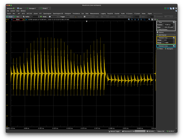
    When I do all of this with, as noted previously above, Scope 1- connected to IN1M and scope 1+ connected to IN1P I get the following disastrous looking results:

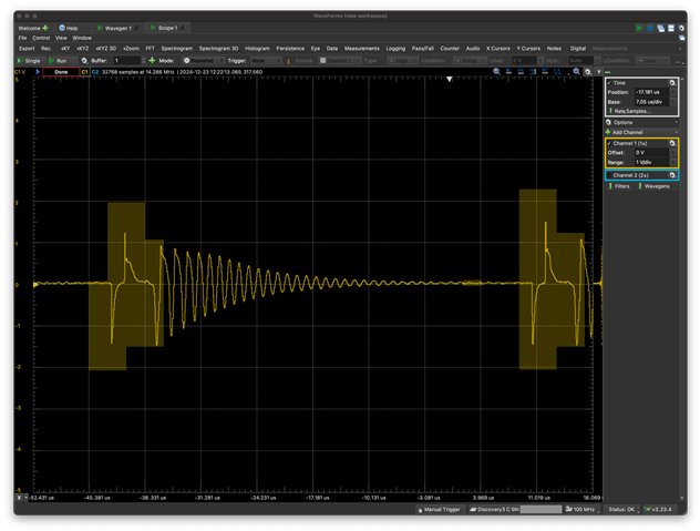
    Zooming in on one of the spikes:

    The slower frequency oscillation appears to be around 19 kHz, and the higher frequency oscillation within that is around 850 kHz. No idea what these area. The MEMS oscillator in the design is the typical 24.576 Mhz.

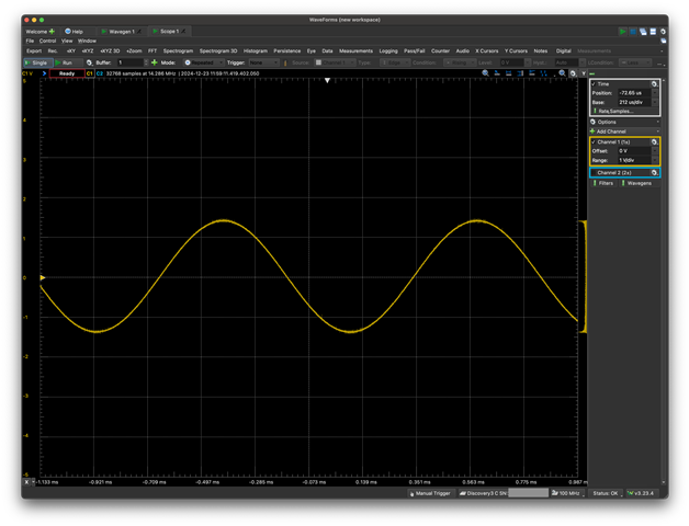
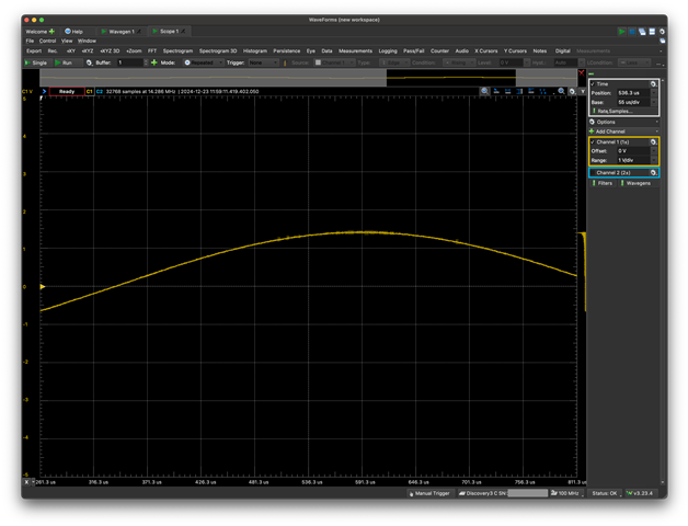
    The above had me confused enough that I also tried doing the exact same thing as above, but with the scope's 1- lead connected to the scope's ground instead of the IN1M input to the codec. Repeating the same experiment gives:

    Which seems very much what I would expect. A fairly clean +/- 1.4V sine wave centered on 0V. Zooming in on that:

    Some noise to be sure. But definitely not what is being heard on the recording, which I will attach separately as before in a moment.

    And ideas from this? Clearly something is very wrong. I'm getting some very large noise signals between IN1P and IN1M. Lots and lots of noise on ground? As I noted earlier due to the board size I was not able to even attempt to keep the analog and digital grounds separated. In my mind that doesn't seem likely to explain what I'm seeing here - I feel like I'm probably missing something that should be obvious.

    -- William

  • Here is the recording of the audio. The 1 kHz tone comes in at around 4 seconds and off again around 14 seconds. It is there, you can hear it. But the noise is just as loud as the signal.

  • Hi William,

    Thanks for the results. Daveon will get back into the office on Thursday after the Christmas holiday.

    Thanks for your patience,
    Jeff McPherson

  • Sounds good, Jeff. Thanks for letting me know. Understood, of course, about the delayed responses at this time of year.

    -- Willliam