This thread has been locked.

If you have a related question, please click the "Ask a related question" button in the top right corner. The newly created question will be automatically linked to this question.

TLV320AIC3120EVM-U: Issues faced with interfacing TLV320AIC3120 EVM with microcontroller over I2S

Part Number: TLV320AIC3120EVM-U
Other Parts Discussed in Thread: TLV320AIC3120

Tool/software:

I am working with TLV320AIC3120 audio codec EVM. I want to control the codec and send and receive data through a microcontroller. I was able to calibrate the registers of codec through I2C using the microcontroller. For that, I have used the TP1 and TP2 test points within the codec and  connected it to the microcontroller. Now, I want to check the data transfer through I2S lines. For that, I am using the TP3,TP4,TP5,TP6 and TP7 test points and connecting it to the microocntroller. First, I need to check whether data transfer is happening from microcontroller over I2S. In my scenario, microcontroller is the master. So, I have enabled I2S Tx as master with sampling frequency of 8 KHz and channel and word length as 16. But, since the codec is getting MCLK from the internal oscillator within the EVM, the microcontroller cannot provide the MCLK. So, I have just connected MCLK pin from the microcontroller to the corresponding test point in the codec EVM and intiialised it as input pin in the controller, so as to synchronize the audio subsystem of the microcontroller and codec. But still, BCLK and WCLK are coming from the microcontroller. I have tried sending the data and even checked the BCLK and WCLK pins, I am expecing 8 KHz at BCLK and 128 KHz at WCLK pin. But, I am not getting it. I have tried sending some example wave file.

/*******************************************************************************
 * File Name:   main.c
 *
 * Description: This is the source code for the Empty Application Example
 *              for ModusToolbox.
 *
 * Related Document: See README.md
 *
 *
 *******************************************************************************
 * Copyright 2021-2024, Cypress Semiconductor Corporation (an Infineon company) or
 * an affiliate of Cypress Semiconductor Corporation.  All rights reserved.
 *
 * This software, including source code, documentation and related
 * materials ("Software") is owned by Cypress Semiconductor Corporation
 * or one of its affiliates ("Cypress") and is protected by and subject to
 * worldwide patent protection (United States and foreign),
 * United States copyright laws and international treaty provisions.
 * Therefore, you may use this Software only as provided in the license
 * agreement accompanying the software package from which you
 * obtained this Software ("EULA").
 * If no EULA applies, Cypress hereby grants you a personal, non-exclusive,
 * non-transferable license to copy, modify, and compile the Software
 * source code solely for use in connection with Cypress's
 * integrated circuit products.  Any reproduction, modification, translation,
 * compilation, or representation of this Software except as specified
 * above is prohibited without the express written permission of Cypress.
 *
 * Disclaimer: THIS SOFTWARE IS PROVIDED AS-IS, WITH NO WARRANTY OF ANY KIND,
 * EXPRESS OR IMPLIED, INCLUDING, BUT NOT LIMITED TO, NONINFRINGEMENT, IMPLIED
 * WARRANTIES OF MERCHANTABILITY AND FITNESS FOR A PARTICULAR PURPOSE. Cypress
 * reserves the right to make changes to the Software without notice. Cypress
 * does not assume any liability arising out of the application or use of the
 * Software or any product or circuit described in the Software. Cypress does
 * not authorize its products for use in any products where a malfunction or
 * failure of the Cypress product may reasonably be expected to result in
 * significant property damage, injury or death ("High Risk Product"). By
 * including Cypress's product in a High Risk Product, the manufacturer
 * of such system or application assumes all risk of such use and in doing
 * so agrees to indemnify Cypress against all liability.
 *******************************************************************************/

/*******************************************************************************
 * Header Files
 *******************************************************************************/
#if defined (CY_USING_HAL)
#include "cyhal.h"
#endif
#include "cybsp.h"

#include "wave.h"

/******************************************************************************
 * Macros
 *******************************************************************************/
#define RXBUF_SIZE            60000
#define MI2C_TIMEOUT_MS     10u         /* in ms */
#define MCLK_CODEC_DELAY_MS 10u         /* in ms */
#define MCLK_FREQ_HZ        16083000u       /* in Hz */
#define MCLK_DUTY_CYCLE     50.0f       /* in %  */
#define USB_CLK_RESET_HZ    100000      /* in Hz */
#define PLL_TIMEOUT_US      12000u      /* in us */
#define PLL_FREQ_FOR_48KHZ  55296000    /* in Hz */
#define PLL_FREQ_FOR_44KHZ  50803200    /* in Hz */

#define MCLK_PIN    P6_4
#define AUDIO_SYS_CLOCK_HZ  98000000u   /* in Hz (Ideally 98.304 MHz) */
#define HFCLK1_CLK_DIVIDER  4u


/*******************************************************************************
 * Global Variables
 *******************************************************************************/
cyhal_i2s_t i2s;
cyhal_clock_t audio_clock;
cyhal_pwm_t mclk_pwm;
cyhal_clock_t audio_clock;
cyhal_clock_t pll_clock;
cyhal_clock_t fll_clock;
cyhal_clock_t system_clock;

const cyhal_i2s_pins_t i2s_tx_pins = {
		.sck  = P5_1,
		.ws   = P5_2,
		.data = P5_3,
		.mclk = P6_4,
};

const cyhal_i2s_config_t i2s_config = {

		.is_tx_slave    = false,    /* TX is Master */
		.is_rx_slave    = false,    /* RX is Master */
		.mclk_hz        = 11289600, /* External MCLK not used */
		.channel_length = 16,       /* In bits */
		.word_length    = 16,       /* In bits */
		.sample_rate_hz = 8000,    /* In Hz */
};


/*******************************************************************************
 * Function Prototypes
 *******************************************************************************/
void i2s_isr_handler(void *arg, cyhal_i2s_event_t event);

/*******************************************************************************
 * Function Definitions
 *******************************************************************************/

/*******************************************************************************
 * Function Name: main
 *********************************************************************************
 * Summary:
 * This is the main function for CPU. It...
 *    1.
 *    2.
 *
 * Parameters:
 *  void
 *
 * Return:
 *  int
 *
 *******************************************************************************/
int main(void)
{
	cy_rslt_t result;

#if defined (CY_DEVICE_SECURE) && defined (CY_USING_HAL)
	cyhal_wdt_t wdt_obj;

	/* Clear watchdog timer so that it doesn't trigger a reset */
	result = cyhal_wdt_init(&wdt_obj, cyhal_wdt_get_max_timeout_ms());
	CY_ASSERT(CY_RSLT_SUCCESS == result);
	cyhal_wdt_free(&wdt_obj);
#endif

	/* Initialize the device and board peripherals */
	result = cybsp_init();

	/* Board init failed. Stop program execution */
	if (result != CY_RSLT_SUCCESS)
	{
		CY_ASSERT(0);
	}

	/* Enable global interrupts */
	__enable_irq();

	/* Initialize the User LED */
	cyhal_gpio_init(CYBSP_USER_LED2, CYHAL_GPIO_DIR_OUTPUT, CYHAL_GPIO_DRIVE_STRONG, CYBSP_LED_STATE_OFF);
	cyhal_gpio_init(CYBSP_USER_LED, CYHAL_GPIO_DIR_OUTPUT, CYHAL_GPIO_DRIVE_STRONG, CYBSP_LED_STATE_OFF);

	// Synchronise MCLK
	cyhal_gpio_init(MCLK_PIN,CYHAL_GPIO_DIR_INPUT,CYHAL_GPIO_DRIVE_NONE,true);
	cyhal_gpio_read(MCLK_PIN);

	/* Initialize the I2S */
	cyhal_i2s_init(&i2s, &i2s_tx_pins, NULL, &i2s_config, NULL);

	cyhal_i2s_register_callback(&i2s, i2s_isr_handler, NULL);
	cyhal_i2s_enable_event(&i2s, CYHAL_I2S_ASYNC_TX_COMPLETE, CYHAL_ISR_PRIORITY_DEFAULT, true);

	/* Start the I2S TX */
	cyhal_i2s_start_tx(&i2s);

	/* If not transmitting, initiate a transfer */
	cyhal_i2s_write_async(&i2s, wave_data, WAVE_SIZE);

	/* Turn ON LED to show a transmission */
	cyhal_gpio_write(CYBSP_USER_LED2, CYBSP_LED_STATE_ON);

	for (;;)
	{
		cyhal_system_delay_ms(10);

	}
}

/*******************************************************************************
 * Function Name: i2s_isr_handler
 ********************************************************************************
 * Summary:
 *  I2S ISR handler. Stop the I2S TX and turn OFF the User LED.
 *
 * Parameters:
 *  arg: not used
 *  event: event that occurred
 *
 *******************************************************************************/
void i2s_isr_handler(void *arg, cyhal_i2s_event_t event)
{
	(void) arg;
	(void) event;

	/* Stop the I2S TX */
	cyhal_i2s_stop_tx(&i2s);

	/* Turn off the LED */
	cyhal_gpio_write(CYBSP_USER_LED, CYBSP_LED_STATE_OFF);
}

/* [] END OF FILE */
Is this configuration having any issue? Is the internal hardware connection in the EVM conflicting with the microcontroller connection? I can even share the code that I have written. Please review it

  • Hi,

    This device does not require an MCLK as the clock input to the PLL/ADC/DAC, you could use BCLK or even apply an external secondary MCLK. However, I would recommend using BCLK as your clock input. To do this, you will need to set registers in the codec to configure this, and to be able to use the ADC/DAC, you will need to configure the device as well. The clock dividers will change depending on your input clocks, but I will assume WCLK=8k and BCLK=256k (8k * 16 bits * 2 channels). It may be beneficial to have a higher BCLK for higher oversampling rate in the device, but for now, we can do a simple divider setup with 256k as the clock into the codec. 

    This is the clock tree from the datasheet. We can set CODEC_CLKIN to BCLK, then NDAC, MDAC, NADC, MADC = 1, and DOSR=AOSR=32 for a DAC_fs and ADC_fs of 8k. 

    The script you would want to use, you can set this after the EVM's initialization script to undo the default PLL settings:

    w 30 04 01 # CODEC_CLKIN = BCLK
    w 30 0b 81 # NDAC=1
    w 30 0c 81 # MDAC=1
    w 30 0d 00 # first values of dosr
    w 30 0e 20 # DOSR = 32
    w 30 12 81 # nadc = 1
    w 30 13 81 # madc = 1
    w 30 20 20 # aosr = 32

    Remember if your MCU is not sending your WCLK and BCLK, then we should not expect any digital audio transfer to work. 

    Also, are you using CodecControl to set up the signal routing in the codec? I recommend it to send I2C to the codec to configure, or to generate I2C for configuring that you can run on your MCU. You can download it here: https://www.ti.com/tool/download/SLAC366 

    Let me know if you need more explanation about all this or more help. I hope it makes sense.

    Best,
    Mir

  • Thank you. In my actual configuration, codec chip does'nt have an external oscillator which provides the clock, so microcontroller will be providing the MCLK. As MCLK does'nt involve in I2S data transfer, it is not mandatory to  initiate MCLK again as a part of I2S, right? Also, to set the required 8 KHz sampling frequency, I can use BCLK as PLL clock, right? But in the codec datahseet, it is mentioned as mono ADC and DAC. So the BCLK will not be  BCLK=256k (8k * 16 bits * 2 channels). Instead it will be BCLK = 128k (8k * 16 bits * 1 channel), right? 

    Also, to monitor the BCLK and WCLK corectly to check whether it is providing exact clock, I should configure the codec and then enable I2S and speak something through the mic, so as to observe the BCLK and MCLK, right?

  • Hi Aarathi,

    The microcontroller can provide the I2S clocks, that is fine. Although the device is a mono codec, it will still need two channels worth of BCLK because I2S expects 2 channels in its definition. So, the right channel of DIN/DOUT audio data would be empty but the clocks would still need to run during that period. Another thing to note is that the input to the PLL must be at least 512kHz, so if you want to use the PLL, then you will either need to use a higher BCLK of 512kHz, or your MCLK as the input to the PLL. The PLL input supports any frequency from 512kHz to 20MHz. I would recommend using the CodecControl software to configure the clock dividers if you are using the PLL, in the "Digital Audio Processing Serial Interface -> Internal Clock Gen Module" screen you can specify your clock input and sample rates and it will generate the PLL parameters and clock dividers for you. To record the I2C that this requires, go to "View->Command" and then click the record button before you select which clock configuration you want. If you don't want to use the PLL, you can just divide down the 256k BCLK signal to 8k, but the OSR will be low so it may not be the highest quality reconstruction of the signal.

    To make sure that the clock is correct, you can enable I2S on your microcontroller and then measure. MCLK, BCLK, and WCLK should all be running when I2S is enabled, only DOUT/DIN will change with an input signal. 

    Let me know if you need more help or explanation.

    Best,
    Mir

  • Hello,

    Thank you for the response. I want to test internal loopback within the codec EVM. I tried programming the 0x1D register within page 0 to enable ADC to DAC loopback. After enabling it through I2C from the microcontroller, I checked the loopback by speaking through the mic and listening back from speaker. But, it is not happening. Can you please provide me with the log for doing ADC to DAC loopback without the intervention of I2S.

  • Hi Aarathi,

    I think the loopback mentioned in register 0x1D is digital loopback, but you're looking for analog loopback (mic to speaker without I2S clocks enabled). For this, you can connect the MIC1LP and/or MIC1RP to the speaker outs with register 0x23. To connect both mic lines to the speakers path and then unmute the speaker driver and headphone drivers:

    w 30 23 70 # connects microphone lines
    w 30 28 06 # HP driver set to 0dB gain
    w 30 24 00 # HP driver 0dB of attenuation
    w 30 2a 04 # speaker driver 6dB of gain
    w 30 26 00 # speaker driver 0dB attenuation

    Let me know if you still have issues with this. Also remember to connect mic bias by connecting jumpers at W2/W3 as specified in the EVM users guide: www.ti.com/lit/ug/slau307/slau307.pdf section 3.4.

    Best,
    Mir

  • Thank you. I have tested with the init log which is provided along with the codec control software once the EVM is detected. With that, to the mic jack I have tried feeding 1 kHz sine wave and tried to listen back through the speaker jack. But I have not configured any other registers apart from the init log registers. Is this method of testing correct? Is this configuration doing ADC to DAC loopback? Also, in the log, I2S is enabled. So is the data going to the digital audio block from ADC output and looped back to the DAC output from the digital audio block? I am attaching the init log that we have used for configuration. Can you please verify it and confirm that this is sufficient to test the internal loopback without sending data over I2S.

    # --------------------------------------------------------------- page 0 is selected 
    w 30 00 00
    # s/w reset
    > 01
    # PLL_clkin = BCLK,codec_clkin = PLL_CLK
    w 30 04 07
    > 91
    > 20
    > 00
    > 00
    # mode is i2s,wordlength is 16
    w 30 1b 00
    # NDAC is powered up and set to 4
    w 30 0b 84
    # MDAC is powered up and set to 4
    > 84
    w 30 12 84
    > 84
    # DOSR = 128, DOSR(9:8) = 0
    > 00
    #             DOSR(7:0) = 128
    > 80
    # DAC => volume control thru pin disable 
    w 30 74 00
    # DAC => drc disable, th and hy
    w 30 44 00
    # DAC => 0 db gain left
    w 30 41 00
    # --------------------------------------------------------------- page 1 is selected
    w 30 00 01
    # De-pop, Power on = 800 ms, Step time = 4 ms
    w 30 21 4e
    # HPL
    w 30 1f c2
    # LDAC routed to HPL
    w 30 23 40
    # HPL unmute and gain 1db
    w 30 28 0e
    # No attenuation on HP
    w 30 24 00
    w 30 25 00
    
    # MIC BIAS = AVDD
    w 30 2e 0b
    # MICPGA P = MIC 10k
    w 30 30 40
    # MICPGA M - CM 10k
    > 40
    # --------------------------------------------------------------- page 0 is selected
    w 30 00 00
    # select DAC DSP mode 11 & enable adaptive filter
    w 30 3c 0b
    w 30 00 08
    w 30 01 04
    w 30 00 00
    # POWERUP DAC (soft step disable)
    w 30 3f d6
    # UNMUTE DAC
    > 00
    # POWERUP ADC channel
    w 30 51 80
    # UNMUTE ADC channel
    > 00
    w 30 00 01
    # Unmute Class-D Left
    w 30 2a 1c
    # Power-up Class-D drivers
    w 30 20 c6
    

  • Hi,

    If you want to test loopback without sending data over I2S, you need to include the line "w 30 23 70", this is what connects the microphone inputs to the output mixer to be sent out the speakers or headphones. In your script, this register is set to 0x40, which only routes the DAC output. 

    If you want to check digital loopback, this connects the input to the ADC once it is converted to digital and the digital input to the DAC. To do this, you can set register 0x1d to 0x30: "w 30 1d 30". I don't see this line in your init log so there is no loopback happening yet.

    Let me know if you are still having issues.

    Best,
    Mir

  • I want to test the digital loopback, i.e., taking data from the mic, routing it through the ADC and taking this digital data to DAC and from there routing it to the speaker. To complete this chain, which all registers should I configure. Also, can you share the sequence of configuring?

  • Also, I dont want to take external data through I2S. I just want to route the same data which is fed from the mic to the speaker through this digital loopback chain.

  • Hi,

    I see, you don't want new I2S data, but you will need to convert the analog input to I2S internally and then route that I2S data back into the DAC path as well. So, you will need I2S clocks. The line "w 30 1d 30" can be set any time after you initialize the device. This is a page 0 register, so make sure you are in page 0 before setting it. You could put it at the end of your script or at the end of the first section before page 1 is selected.

    This is the register specified by "1d", by setting it to 0x30 we enabled both DIN-to-DOUT loopback and ADC-to-DAC loopback, but if you want just analog in, through the ASI, then analog out, you do not need DIN-to-DOUT loopback enabled. So, if you prefer, you could set register 0x1d to 0x10, changing the command to "w 30 1d 10". I would recommend this instead from what you describe.

    Best,
    Mir

  • I have one more query. I want to send a data greater than 1 minute through the mic, which needs to be digitized and transmitted over I2S to PSoC at 128 kbps. I just want to know can I send the whole data all at once over I2S to the microcontroller or do I need to segment it. Similarly in the reception side, is there any limitation in the data size over I2S?

  • Hi Aarathi,

    This depends on what your I2S host is capable of. However, per the I2S spec there is no reason you can't play more than 1 minute of audio data. We've done so many times.

    Best regards,
    Jeff McPherson

  • Thank you. I have done the ADC to DAC loopback, and it is successful. Now, I have enabled I2S, and I am providing MCLK, WCLK and BCLK from the external microcontroller. I want to send data from microcontroller over I2S to the codec and check whether it is reaching the codec or the inverse, i.e., sending data from codec through mic over I2S to microcontroller and check the data. How to do this?

  • Hi Aarathi,

    Glad you got the loopback working. The I2S audio signals are sent/received on the DIN/DOUT pins. DIN would be digital audio in for the DAC, and DOUT will be digital audio out for the ADC. You will want to disable loopback with register 29 as shown before. Do you have a new register configuration that you are using? If you are having issues with ADC or DAC operation we can take a better look at your config. 

    Best,
    Mir

  • Hi,

    I have configured the register 29 with 0x00, so as to disable the loopback and also I have enabled I2S by configuring register 27 with 0x00. Apart from that, I have kept all other registers the same. Now, I have given I2S clocks, i.e., WCLK and BCLK from the microcontroller. I have configured I2S TX as master and started sending data from the microcontroller. So, I should get the data through speaker, right? But I am not able to listen to anything, even though I am sending 128 kbps decoded pcm data from microcontroller. Can you help me in this? I am givng an MCLK of 4 MHz.

  • Hi,

    Today is a holiday for our team in the U.S. We will follow up with you on Tuesday.

    Thank you for your patience,
    Jeff McPherson

  • What is your WCLK and BCLK? Can you send an updated I2C script? Sorry about this delay. 

    Best,
    Mir

  • The WCLK that I have programmed is 8 KHz and BCLK is 256 KHz. I have enabled DIN to DOUT loopack, just to check whether the data transfer over I2S line is happening or not. But it is not coming as expected. I am attaching the log that I am using for my testing.

    # --------------------------------------------------------------- page 0 is selected
    w 30 00 00
    # s/w reset
    > 01
    # PLL_clkin = MCLK,codec_clkin = PLL_CLK
    w 30 04 03
    > D4
    > 20
    > 00
    > 00
    # mode is i2s,wordlength is 16
    # dac configurations
    w 30 1b 00
    w 30 1c 02
    # NDAC is powered up and set to 4
    w 30 0b E7
    # MDAC is powered up and set to 4
    > 81
    > 00
    > 01
    w 30 19 05
    > 80
    w 30 33 10
    w 30 3C 04
    > 04
    
    # adc configurations
    w 30 12 E7
    > 81
    > 80
    # DAC => volume control thru pin disable
    w 30 74 00
    # DAC => drc disable, th and hy
    w 30 44 00
    # DAC => 0 db gain left
    w 30 41 10
    # --------------------------------------------------------------- page 1 is selected
    w 30 00 01
    # De-pop, Power on = 800 ms, Step time = 4 ms
    w 30 21 4e
    # HPL
    w 30 1f 86
    # LDAC routed to HPL
    w 30 23 40
    # HPL unmute and gain 1db
    w 30 28 0e
    # No attenuation on HP
    w 30 24 00
    w 30 25 00
    
    # MIC BIAS = AVDD
    w 30 2e 0A
    w 30 2f 80
    # MICPGA P = MIC 10k
    w 30 30 10
    # MICPGA M - CM 10k
    > 40
    # --------------------------------------------------------------- page 0 is selected
    w 30 00 00
    # select DAC DSP mode 11 & enable adaptive filter
    w 30 3c 0b
    w 30 00 08
    w 30 01 04
    w 30 00 00
    # POWERUP DAC (soft step disable)
    w 30 3f d6
    # UNMUTE DAC
    > 04
    # POWERUP ADC channel
    w 30 51 80
    # UNMUTE ADC channel
    > 00
    w 30 00 01
    # Unmute Class-D Left
    w 30 2a 1c
    # Power-up Class-D drivers
    w 30 20 c6
    w 30 26 A3
    w 30 00 01
    w 30 20 06
    w 30 00 00
    w 30 1d 20
    w 30 1e 82
    w 30 00 00


  • Hi Aarathi,

    Most likely your issue with the digital audio now is that you set the CODEC_CLKIN clock to be the PLL clock, but PLL is not enabled. Also, if you are not using MCLK and instead BCLK as the input clock, the device does not have a sufficient oversampling ratio (OSR). This is the last step in the clock tree, and the lowest OSR possible for some processing blocks to operate would be 32. This would require that your NDAC and MDAC=1, and then the OSR would be 32. We can try this first, and if there are still issues, you can enable the PLL to multiply up the clocks so that you get an OSR of 128.

    I have written out a clock configuration for you without the PLL enabled (giving OSR of 32). To enable the PLL, we need an input clock of at least 512kHz, so if you have an MCLK in the system that is higher than BCLK, or if you could increase your input clock to 512k, then we can enable the PLL and enable a 128 OSR. Let me know if you have MCLK in the system.

    Set this clock config before the input/output config and remove your current clock settings:

    # OSR of 32, PLL not used:
    w 30 04 05 #PLL_CLKIN=BCLK (unused), CODEC_CLKIN=BCLK
    w 30 05 11 #PLL powered down, P=1, R=1
    w 30 06 01 #J=1
    w 30 07 00 #D=0
    w 30 08 00 #D=0
    w 30 0b 81 #NDAC powered up, divider=1
    w 30 0c 81 #MDAC powered up, divider=1
    w 30 0d 00 #OSR MSB
    w 30 0e 20 #DAC DOSR=32
    w 30 12 01 #set ADC_DSP_CLK to DAC_DSP_CLK
    w 30 13 01 #set ADC_MOD_CLK to DAC_MOD_CLK
    w 30 14 20 #ADC AOSR = 32

    Best,
    Mir

  • I have configured the clocks according to the log that you shared,. i.e., providing BCLK as the PLL clock, disabling the PLL and providing CODEC_CLKIN as BCLK.  In my case, microcontroller is the master. The MCLK to the codec is given from the microcontroller. I have given an MCLK of 4 MHz from the controller and observed the data. I have enabled I2S and tried sending some bytes of data over I2S to codec. But, I observed some synchronization issue between WCLK and the data bytes coming to the DIN. Even though data bytes are coming correctly over the DIN pin, the synchronization is not proper. Is there any particular limitation in the MCLK to be provided to the codec? If yes, can you tell me what MCLK should I program? I am attaching the screenshot of the plots that we got in logic analyzer, where I have probed WCLK and DIN. BCLK is coming as expected 
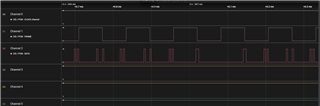
16 bits per each WCLK.

  • If you are having issues sending I2S over DIN and synchronization with your WCLK, this is an issue with your microcontroller sending the digital audio data. 

    If you are using MCLK=4MHz, you can configure the PLL as follows to get an oversampling rate of 128:

    w 30 04 03 #PLL_CLKIN=MCLK, CODEC_CLKIN=PLL_CLK
    w 30 05 d4 #power up PLL, P=5, R=4
    w 30 06 20 #J=32
    w 30 07 00 #D=0
    w 30 08 00 #D=0
    w 30 0b 84 #NDAC=4
    w 30 0c 99 #MDAC=25
    w 30 0d 00 #DOSR MSB=0
    w 30 0e 80 #DOSR=128
    w 30 12 84 #NADC=4
    w 30 13 99 #MADC=25
    w 30 14 80 #AOSR=128

    Let me know if you have issues with this configuration.

    Best,
    Mir

  • I am using the previous log that you shared, i.e., setting PLL CLK as BCLK and powering off the PLL. With that log and providing MCLK from the microcontroller, I tried sending some example wave data.pcm from the microcontroller by enabling I2S. I am still keeping ADC and DAC powered on. But, I am not getting the expected audio out of the speaker. I guess there is something I am missing in the I2C configuration. Or is it a must to power off ADC when we are only testing the receiver chain? To test this scenario, can you provide the complete log. I will tell my requirement:

    1. MCLK provided from PSOC as 2 MHz, as according to the I2S configuration requirement of microcontroller, to get 8 KHz sampling rate, we should give 2 MHz MCLK.

    2. Since I am giving MCLK as 2 MHz, I am not giving MCLK as PLL CLK, instead PLL CLK is given as BCLK, which is 256 KHz. CODEC CLKIN is also given as BCLK.

    3. I need to power on DAC, as I am checking receiver chain.

    4. I need to enable I2S.

    5. I need to route the DAC output to the MUX, so that the data is routed to the HPOUT

    Similarly, I am planning for a test, where MIC data will be captured and send over I2S to the microcontroller. The microcontroller will save this data and again send it back over I2S to the DAC, so that we will be able to listen back the audio which is sent from the MIC. Can you please assist me in completing this test? Eventually, I need to ensure that data transfer is properly happening over I2S.

    Also, I have one more doubt. Each data should be of 16 bits right? So should I expect one data, i.e., 16 bits data corresponding to 1 WCLK? And can it be in the positive as well as negative side of WCLK?

  • Hi Aarathi,

    Sorry about the delay, I will be able to give you a register setting for the 2MHz MCLK config tomorrow. As for the clock data, for I2S, you would expect 16 bits per positive side and 16 bits per negative side of the WCLK signal, this is for each channel of the data. So, you would want your BCLK to be 16 * 2 * fs, which 256kHz BCLK is the correct frequency for this configuration.

    -Mir

  • Okay. Thank you so much. Also, I would like to know which all registers should I configure to enable the SPKP and SPKN lines. Right now, for loopback test I have enabled HPOUT. So, by connecting speaker to the external jack I was able to listen to the audio. Now, I need to route the DAC output to the SPK P and SPK N, so that I can listen through the speaker which is connected in my board.

  • Hi Aarathi,

    To enable SPKP and SPKN, you should change registers 38 and 42 from page 1 as shown in the block diagram from the datasheet:


    It might look like this:

    w 30 00 01 #page 1
    w 30 23 40 #dac routed to the mixer amplifier
    w 30 26 80 #analog volume control output routed to class d amp, set to 0 gain
    w 30 2a 04 #class D driver is not muted, output stage gain=6dB
    

    Also, for the clock config, you will need MCLK to be 4MHz and not 2MHz, there is no good PLL config for a 2MHz MCLK. Other MCLKs that would work would be a multiple of 8k. You can test out configurations with the CodecControl software, or let me know what other options you could use and I can check for you. You can read more about PLL input requirements in section 7.3.13.1 of the datasheet. 

    Best,
    Mir

  • Thank you. Even though I am giving MCLK 2 MHz and PLL clock as MCLK, PLL is powered down. So that will not be an issue, right? And for this configuration, I am getting ADC fs as 8 KHz also from the codec control software.

  • Hi Aarathi,

    Yes, you will need to power on the PLL as I directed in the last big block of code I provided, with an MCLK of 4MHz. If you want to use the device without the PLL, you can run it with the BCLK as the input clock, as I showed in the code provided before that. Running the device at an MCLK of 2MHz is not recommended and may lead to errors... can you send a screenshot of your codec control software config that is letting you choose 8k? What is your current configuration, are you having audio issues or did it work?

    Best,
    Mir

  • Hi,

    Right now, I have configured the PLL with PLL powered down and giving BCLK as CODEC CLKIN and the ADC to DAC loopback is working fine. I wanted only DAC output to go to HP OUT. The register that I have configured for setting this is Page 1 / Register 35 with 0x80. But still, I am listening some leakage signal coming from the MIC1RP. Why is it happening? Is there anything more to be configured?

  • Hi,

    Can you post your full set of i2c commands for this configuration? As well as a register dump to make sure it worked?

    You may also want to try to connect the DAC to the mixer amplifier, setting register 0x23 to 0x40 instead of 0x80. This allows another gain stage and would be another thing to try. Let me know if it helps or if you still have leakage. Also, make sure register 0x1d is set to 0x00, to disable the loopback.

    Best,
    Mir

  • Hi,

    I am configuring 0x23 with 0X40. I have tried feeding 1 KHz sine wave through the mic, taking it through the ADC, over I2S to the microcontroller. Microcontroller will send the data back to codec over I2S, which then passes over DAC to the mixer. From there, to the speaker. But, I am getting a distorted sine wave. I will attach the code.

    /*******************************************************************************
     * File Name:   main.c
     *
     * Description: This example project demonstrates the basic operation of the
     * I2C resource as Master using HAL APIs. The I2C master sends the
     * command packets to the I2C slave to control an user LED.
     *
     * Related Document: See README.md
     *
     *
     *******************************************************************************
     * Copyright 2019-2024, Cypress Semiconductor Corporation (an Infineon company) or
     * an affiliate of Cypress Semiconductor Corporation.  All rights reserved.
     *
     * This software, including source code, documentation and related
     * materials ("Software") is owned by Cypress Semiconductor Corporation
     * or one of its affiliates ("Cypress") and is protected by and subject to
     * worldwide patent protection (United States and foreign),
     * United States copyright laws and international treaty provisions.
     * Therefore, you may use this Software only as provided in the license
     * agreement accompanying the software package from which you
     * obtained this Software ("EULA").
     * If no EULA applies, Cypress hereby grants you a personal, non-exclusive,
     * non-transferable license to copy, modify, and compile the Software
     * source code solely for use in connection with Cypress's
     * integrated circuit products.  Any reproduction, modification, translation,
     * compilation, or representation of this Software except as specified
     * above is prohibited without the express written permission of Cypress.
     *
     * Disclaimer: THIS SOFTWARE IS PROVIDED AS-IS, WITH NO WARRANTY OF ANY KIND,
     * EXPRESS OR IMPLIED, INCLUDING, BUT NOT LIMITED TO, NONINFRINGEMENT, IMPLIED
     * WARRANTIES OF MERCHANTABILITY AND FITNESS FOR A PARTICULAR PURPOSE. Cypress
     * reserves the right to make changes to the Software without notice. Cypress
     * does not assume any liability arising out of the application or use of the
     * Software or any product or circuit described in the Software. Cypress does
     * not authorize its products for use in any products where a malfunction or
     * failure of the Cypress product may reasonably be expected to result in
     * significant property damage, injury or death ("High Risk Product"). By
     * including Cypress's product in a High Risk Product, the manufacturer
     * of such system or application assumes all risk of such use and in doing
     * so agrees to indemnify Cypress against all liability.
     *******************************************************************************/
    
    /*******************************************************************************
     * Header Files
     *******************************************************************************/
    #include "cyhal.h"
    #include "cybsp.h"
    #include <stdio.h>
    //#include "cy_retarget_io.h"
    #include "wave.h"
    
    /*******************************************************************************
     * Macros
     *******************************************************************************/
    /* I2C bus frequency */
    #define I2C_FREQ              (100000UL)// (400000UL)
    
    #define DELAY                   5
    #define DELAY1                  5
    //#define DEBOUNCE_DELAY_MS      10
    cyhal_clock_t system_clock;
    cyhal_clock_t fll_clock;
    
    
    /* Master I2C Settings */
    #define MI2C_TIMEOUT_MS     10u         /* in ms */
    /* Note that we are not able to achieve the desired frequency, so we round up
     *  the frequency values to avoid mismatches */
    /* Master Clock (MCLK) Settings */
    #define MCLK_FREQ_HZ        3072000//2048000//4083000//4000000//11280000////    /* in Hz (Ideally 10.96 MHz) */
    #define MCLK_DUTY_CYCLE     50.0f       /* in %  */
    /* Clock Settings */
    #define AUDIO_SYS_CLOCK_HZ  32768000//98000000u   /* in Hz (Ideally 98.304 MHz) */
    /* PWM MCLK Pin */
    #define MCLK_PIN            P5_0
    /* Debounce delay for the button */
    #define DEBOUNCE_DELAY_MS   10        /* in ms */
    /* HFCLK1 Clock Divider */
    #define HFCLK1_CLK_DIVIDER  16u//4u
    
    #define CODEC_I2C_SCL P9_0
    #define CODEC_I2C_SDA P9_1
    
    
    #define I2C_TIMEOUT_MS         10    // Timeout for I2C communication
    #define AUDIO_CODEC_I2C_ADDR   0x18  // I2C address of the codec (7-bit address)
    #define PACKET_SIZE            2
    //#define MCLK_PIN            P5_0
    //#define MCLK_FREQ_HZ        4083000//4000000//11280000////    /* in Hz (Ideally 10.96 MHz) */
    //#define MCLK_DUTY_CYCLE     50.0f       /* in %  */
    
    #define USER_LED P8_5
    #define USER_LED2 P8_6
    
    #define USER_BTN P10_6
    #define AUDIOCODEC_RESET P9_6
    /*******************************************************************************
     * Global Variables
     *******************************************************************************/
    cyhal_i2c_t mI2C;
    cyhal_i2c_cfg_t mI2C_cfg;
    cyhal_pwm_t mclk_pwm;
    cyhal_clock_t audio_clock;
    cyhal_i2s_t i2s;
    cyhal_clock_t pll_clock;
    
    const cyhal_i2s_pins_t i2s_pins = {
    		.sck  = P5_1,
    		.ws   = P5_2,
    		.data = P5_3,
    		.mclk = NC,
    };
    
    const cyhal_i2s_pins_t i2s_tx_pins = {
    		.sck  = P5_1,
    		.ws   = P5_2,
    		.data = P5_3,
    		.mclk = NC
    };
    
    const cyhal_i2s_pins_t i2s_rx_pins = {
    		.sck  = P5_4,
    		.ws   = P5_5,
    		.data = P5_6,
    		.mclk = NC
    
    };
    
    const cyhal_i2s_config_t i2s_config = {
    		.is_tx_slave    = true,    /* TX is Master */
    		.is_rx_slave    = false,    /* RX not used */
    		.mclk_hz        = 0,        /* External MCLK not used */
    		.channel_length = 16,       /* In bits */
    		.word_length    = 16,       /* In bits */
    		.sample_rate_hz = 8000,    /* In Hz */
    };
    
    
    void i2s_isr_handler(void *arg, cyhal_i2s_event_t event)
    {
    	(void) arg;
    	(void) event;
    
    	/* Stop the I2S TX */
    	cyhal_i2s_stop_tx(&i2s);
    
    	/* Turn off the LED */
    	//cyhal_gpio_write(CYBSP_USER_LED, CYBSP_LED_STATE_OFF);
    }
    
    /*******************************************************************************
     * Function Prototypes
     *******************************************************************************/
    
    /*******************************************************************************
     * Function Definitions
     *******************************************************************************/
    /*******************************************************************************
     * Function Name: handle_error
     ********************************************************************************
     * Summary:
     * User defined error handling function
     *
     * Parameters:
     *  uint32_t status - status indicates success or failure
     *
     * Return:
     *  void
     *
     *******************************************************************************/
    void handle_error(uint32_t status)
    {
    	if (status != CY_RSLT_SUCCESS)
    	{
    		CY_ASSERT(0);
    	}
    }
    
    void clock_init(void)
    {
    	/* Initialize the PLL */
    	cyhal_clock_reserve(&pll_clock, &CYHAL_CLOCK_PLL[0]);
    	cyhal_clock_set_frequency(&pll_clock, AUDIO_SYS_CLOCK_HZ, NULL);
    	cyhal_clock_set_enabled(&pll_clock, true, true);
    
    	/* Initialize the audio subsystem clock (HFCLK1) */
    	cyhal_clock_reserve(&audio_clock, &CYHAL_CLOCK_HF[1]);
    	cyhal_clock_set_source(&audio_clock, &pll_clock);
    
    	/* Drop HFCK1 frequency for power savings */
    	cyhal_clock_set_divider(&audio_clock, HFCLK1_CLK_DIVIDER);
    	cyhal_clock_set_enabled(&audio_clock, true, true);
    
    	/* Initialize the system clock (HFCLK0) */
    	cyhal_clock_reserve(&system_clock, &CYHAL_CLOCK_HF[0]);
    	cyhal_clock_set_source(&system_clock, &pll_clock);
    
    	/* Disable the FLL for power savings */
    	cyhal_clock_reserve(&fll_clock, &CYHAL_CLOCK_FLL);
    	cyhal_clock_set_enabled(&fll_clock, false, true);
    }
    
    void i2c_init(void){
    	cy_rslt_t result;
    
    	mI2C_cfg.is_slave = false;
    	mI2C_cfg.address = 0;
    	mI2C_cfg.frequencyhal_hz = I2C_FREQ;
    	/* Init I2C master */
    	result = cyhal_i2c_init(&mI2C, CODEC_I2C_SDA, CODEC_I2C_SCL, NULL);
    	/* I2C master init failed. Stop program execution */
    	handle_error(result);
    
    	/* Configure I2C Master */
    	result = cyhal_i2c_configure(&mI2C, &mI2C_cfg);
    	/* I2C master configuration failed. Stop program execution */
    	handle_error(result);
    
    }
    
    void audio_codec_i2c_write_reg(uint8_t reg,uint8_t data){
    	uint8_t buffer[2] = {reg,data};
    	//cyhal_i2c_t mI2C;
    	cyhal_i2c_master_write(&mI2C, AUDIO_CODEC_I2C_ADDR,buffer, PACKET_SIZE, 0, true);
    	cyhal_system_delay_ms(DELAY);
    }
    
    
    void audio_codec_i2c_read_reg(uint8_t reg, uint8_t *Data){
    
    	//cyhal_i2c_t mI2C;
    	//uint8_t reg_add[2] = {reg, 0};
    	uint8_t rx_buffer[2]= {0};
    
    	cyhal_i2c_master_write(&mI2C,AUDIO_CODEC_I2C_ADDR,&reg,1,0,true);
    
    	cyhal_i2c_master_read(&mI2C, AUDIO_CODEC_I2C_ADDR, &rx_buffer[0], 1,0, true);
    
    	cyhal_gpio_write(USER_LED2, false);
    	*Data = rx_buffer[0];
    	cyhal_system_delay_ms(DELAY);
    
    }
    /*******************************************************************************
     * Function Name: main
     ********************************************************************************
     * Summary:
     * This is the main function.
     *   1. I2C Master sends command packet to the slave
     *   2. I2C Master reads the response packet to generate the next command
     *
     * Parameters:
     *  void
     *
     * Return:
     *  int
     *
     *******************************************************************************/
    int main(void)
    {
    	cy_rslt_t result;
    	uint8_t rx_buf[60] = {0} ;
    
    	uint8_t icount = 0;
    	volatile uint8_t i =0;
    
    	/* Initialize the device and board peripherals */
    	result = cybsp_init();
    	/* Board init failed. Stop program execution */
    	//handle_error(result);
    
    	mI2C_cfg.is_slave = false;
    	mI2C_cfg.address = 0;
    	mI2C_cfg.frequencyhal_hz = I2C_FREQ;
    
    	/* Init I2C master */
    	result = cyhal_i2c_init(&mI2C, CODEC_I2C_SDA, CODEC_I2C_SCL, NULL);
    	/* I2C master init failed. Stop program execution */
    	handle_error(result);
    
    	/* Configure I2C Master */
    	result = cyhal_i2c_configure(&mI2C, &mI2C_cfg);
    	/* I2C master configuration failed. Stop program execution */
    	handle_error(result);
    
    	//i2c_init();
    
    #if defined(KIT_XMC72)
    	/*Configure clock settings for KIT_XMC72_EVK */
    	cyhal_clock_t clock_fll, clock_hf, clock_peri;
    	result = cyhal_clock_reserve(&clock_hf, &CYHAL_CLOCK_HF[0]);
    	result = cyhal_clock_reserve(&clock_fll, &CYHAL_CLOCK_FLL);
    	if(result == CY_RSLT_SUCCESS){
    		result = cyhal_clock_set_source(&clock_hf, &clock_fll);
    	}
    	/* Set divider to 1 for Peripheral Clock */
    	result = cyhal_clock_reserve(&clock_peri, CYHAL_CLOCK_PERI);
    	if(result == CY_RSLT_SUCCESS){
    		result = cyhal_clock_set_divider(&clock_peri,1);
    	}
    #endif
    
    
    	/* Initialize the User LED */
    	cyhal_gpio_init(USER_LED2, CYHAL_GPIO_DIR_OUTPUT, CYHAL_GPIO_DRIVE_STRONG, CYBSP_LED_STATE_OFF);
    	cyhal_gpio_init(USER_LED, CYHAL_GPIO_DIR_OUTPUT, CYHAL_GPIO_DRIVE_STRONG, CYBSP_LED_STATE_OFF);
    
    	cyhal_gpio_init(AUDIOCODEC_RESET, CYHAL_GPIO_DIR_OUTPUT, CYHAL_GPIO_DRIVE_STRONG,1);
    	cyhal_gpio_write(AUDIOCODEC_RESET,0);
    	cyhal_system_delay_ms(10);
    	cyhal_gpio_write(AUDIOCODEC_RESET,1);
    
    	/* Board init failed. Stop program execution */
    	if (result != CY_RSLT_SUCCESS)
    	{
    		CY_ASSERT(0);
    	}
    
    	/* Enable interrupts */
    	__enable_irq();
    
    	/* Init the clocks */
    	clock_init();
    
    	/* Initialize the Master Clock with a PWM */
    	cyhal_pwm_init(&mclk_pwm, MCLK_PIN, NULL);
    	cyhal_pwm_set_duty_cycle(&mclk_pwm, MCLK_DUTY_CYCLE, MCLK_FREQ_HZ);
    	cyhal_pwm_start(&mclk_pwm);
    
    	/* Initialize the I2S */
    
    	//cyhal_i2s_init(&i2s, NULL, &i2s_rx_pins, &i2s_config, &audio_clock);
    	cyhal_i2s_init(&i2s, &i2s_tx_pins, &i2s_rx_pins, &i2s_config, &audio_clock);
    	cyhal_i2s_register_callback(&i2s, i2s_isr_handler, NULL);
    	cyhal_i2s_enable_event(&i2s, CYHAL_I2S_ASYNC_TX_COMPLETE, CYHAL_ISR_PRIORITY_DEFAULT, true);
    
    	/* Wait for the MCLK to clock the audio codec */
    	cyhal_system_delay_ms(1);
    
    	//configure I2C registers
    
    	audio_codec_i2c_write_reg(0x00,0x00);
    	audio_codec_i2c_read_reg(0x00,&rx_buf[0]);
    	cyhal_system_delay_ms(DELAY1);
    
    	audio_codec_i2c_write_reg(0x01,0x01);
    	audio_codec_i2c_read_reg(0x01,&rx_buf[1]);
    	cyhal_system_delay_ms(DELAY1);
    
    	//	audio_codec_i2c_write_reg(0x04,0x05/*0x03*/);
    	audio_codec_i2c_write_reg(0x04,0x00/*0x03*/);
    	audio_codec_i2c_read_reg(0x04,&rx_buf[2]);
    	cyhal_system_delay_ms(DELAY1);
    
    	//	audio_codec_i2c_write_reg(0x05,0x11/*0xD4*/);
    	audio_codec_i2c_write_reg(0x05,0x11/*0xD4*/);
    	audio_codec_i2c_read_reg(0x05,&rx_buf[3]);
    	cyhal_system_delay_ms(DELAY1);
    
    	audio_codec_i2c_write_reg(0x06,0x01/*0x20*/);
    	audio_codec_i2c_read_reg(0x06,&rx_buf[4]);
    	cyhal_system_delay_ms(DELAY1);
    
    	audio_codec_i2c_write_reg(0x07,0x00);
    	audio_codec_i2c_read_reg(0x07,&rx_buf[5]);
    	cyhal_system_delay_ms(DELAY1);
    
    	audio_codec_i2c_write_reg(0x08,0x00);
    	audio_codec_i2c_read_reg(0x08,&rx_buf[6]);
    	cyhal_system_delay_ms(DELAY1);
    
    	audio_codec_i2c_write_reg(0x1B,0x00);
    	audio_codec_i2c_read_reg(0x1B,&rx_buf[7]);
    	cyhal_system_delay_ms(DELAY1);
    
    	audio_codec_i2c_write_reg(0x1C,0x02);
    	audio_codec_i2c_read_reg(0x1C,&rx_buf[8]);
    	cyhal_system_delay_ms(DELAY1);
    
    	audio_codec_i2c_write_reg(0x0B,0x81/*0xE7*/);
    	audio_codec_i2c_read_reg(0x0B,&rx_buf[9]);
    	cyhal_system_delay_ms(DELAY1);
    
    	//	audio_codec_i2c_write_reg(0x0C,0x81);
    	audio_codec_i2c_write_reg(0x0C,0x83);
    	audio_codec_i2c_read_reg(0x0C,&rx_buf[10]);
    	cyhal_system_delay_ms(DELAY1);
    
    	audio_codec_i2c_write_reg(0x0D,0x00);
    	audio_codec_i2c_read_reg(0x0D,&rx_buf[11]);
    	cyhal_system_delay_ms(DELAY1);
    
    	//	audio_codec_i2c_write_reg(0x0E,0x20/*0x01*/);
    	audio_codec_i2c_write_reg(0x0E,0x80/*0x01*/);
    	audio_codec_i2c_read_reg(0x0E,&rx_buf[12]);
    	cyhal_system_delay_ms(DELAY1);
    
    	audio_codec_i2c_write_reg(0x19,0x05);
    	audio_codec_i2c_read_reg(0x19,&rx_buf[13]);
    	cyhal_system_delay_ms(DELAY1);
    
    	audio_codec_i2c_write_reg(0x20,0x80);
    	audio_codec_i2c_read_reg(0x20,&rx_buf[14]);
    	cyhal_system_delay_ms(DELAY1);
    
    	audio_codec_i2c_write_reg(0x33,0x10);
    	audio_codec_i2c_read_reg(0x33,&rx_buf[15]);
    	cyhal_system_delay_ms(DELAY1);
    
    	audio_codec_i2c_write_reg(0x3C,0x04);
    	audio_codec_i2c_read_reg(0x3C,&rx_buf[16]);
    	cyhal_system_delay_ms(DELAY1);
    
    	audio_codec_i2c_write_reg(0x3D,0x04);
    	audio_codec_i2c_read_reg(0x3D,&rx_buf[17]);
    	cyhal_system_delay_ms(DELAY1);
    
    	//	audio_codec_i2c_write_reg(0x12,0x01/*0xE7*/);
    	audio_codec_i2c_write_reg(0x12,0x81/*0xE7*/);
    	audio_codec_i2c_read_reg(0x12,&rx_buf[18]);
    	cyhal_system_delay_ms(DELAY1);
    
    	//	audio_codec_i2c_write_reg(0x13,0x01/*0x81*/);
    	audio_codec_i2c_write_reg(0x13,0x83/*0x81*/);
    	audio_codec_i2c_read_reg(0x13,&rx_buf[19]);
    	cyhal_system_delay_ms(DELAY1);
    
    	//	audio_codec_i2c_write_reg(0x14,0x20/*0x80*/);
    	audio_codec_i2c_write_reg(0x14,0x80/*0x80*/);
    	audio_codec_i2c_read_reg(0x14,&rx_buf[20]);
    	cyhal_system_delay_ms(DELAY1);
    
    	audio_codec_i2c_write_reg(0x74,0x00);
    	audio_codec_i2c_read_reg(0x74,&rx_buf[21]);
    	cyhal_system_delay_ms(DELAY1);
    
    	audio_codec_i2c_write_reg(0x44,0x00);
    	audio_codec_i2c_read_reg(0x44,&rx_buf[22]);
    	cyhal_system_delay_ms(DELAY1);
    
    	audio_codec_i2c_write_reg(0x41,0x10);
    	audio_codec_i2c_read_reg(0x41,&rx_buf[23]);
    	cyhal_system_delay_ms(DELAY1);
    
    	audio_codec_i2c_write_reg(0x00,0x01);
    	audio_codec_i2c_read_reg(0x00,&rx_buf[24]);
    	cyhal_system_delay_ms(DELAY1);
    
    	audio_codec_i2c_write_reg(0x21,0x4E);
    	audio_codec_i2c_read_reg(0x21,&rx_buf[25]);
    	cyhal_system_delay_ms(DELAY1);
    
    	audio_codec_i2c_write_reg(0x1F,0x86);
    	audio_codec_i2c_read_reg(0x1F,&rx_buf[26]);
    	cyhal_system_delay_ms(DELAY1);
    
    	//audio_codec_i2c_write_reg(0x23,0x40);// DAC output routed to the mixer amplifier
    	audio_codec_i2c_write_reg(0x23,0x80); // DAC output routed directly to HPOUT
    	audio_codec_i2c_read_reg(0x23,&rx_buf[27]);
    	cyhal_system_delay_ms(DELAY1);
    
    	audio_codec_i2c_write_reg(0x28,0x0E);
    	audio_codec_i2c_read_reg(0x28,&rx_buf[28]);
    	cyhal_system_delay_ms(DELAY1);
    
    	audio_codec_i2c_write_reg(0x24,0x00);
    	audio_codec_i2c_read_reg(0x24,&rx_buf[29]);
    	cyhal_system_delay_ms(DELAY1);
    
    	audio_codec_i2c_write_reg(0x25,0x00);
    	audio_codec_i2c_read_reg(0x25,&rx_buf[30]);
    	cyhal_system_delay_ms(DELAY1);
    
    	audio_codec_i2c_write_reg(0x2E,0x0A);
    	//audio_codec_i2c_write_reg(0x2E,0x00); //MICBIAS powered down
    	audio_codec_i2c_read_reg(0x2E,&rx_buf[31]);
    	cyhal_system_delay_ms(DELAY1);
    
    	audio_codec_i2c_write_reg(0x2F,0x80);
    	audio_codec_i2c_read_reg(0x2F,&rx_buf[32]);
    	cyhal_system_delay_ms(DELAY1);
    
    	//audio_codec_i2c_write_reg(0x30,0x10);
    	audio_codec_i2c_write_reg(0x30,0x40);
    	audio_codec_i2c_read_reg(0x30,&rx_buf[33]);
    	cyhal_system_delay_ms(DELAY1);
    
    	audio_codec_i2c_write_reg(0x31,0x40);
    	audio_codec_i2c_read_reg(0x31,&rx_buf[34]);
    	cyhal_system_delay_ms(DELAY1);
    
    	audio_codec_i2c_write_reg(0x00,0x00);
    	audio_codec_i2c_read_reg(0x00,&rx_buf[35]);
    	cyhal_system_delay_ms(DELAY1);
    
    	audio_codec_i2c_write_reg(0x3C,0x0B);
    	audio_codec_i2c_read_reg(0x3C,&rx_buf[36]);
    	cyhal_system_delay_ms(DELAY1);
    
    	audio_codec_i2c_write_reg(0x00,0x08);
    	audio_codec_i2c_read_reg(0x00,&rx_buf[37]);
    	cyhal_system_delay_ms(DELAY1);
    
    	audio_codec_i2c_write_reg(0x01,0x04);
    	audio_codec_i2c_read_reg(0x01,&rx_buf[38]);
    	cyhal_system_delay_ms(DELAY1);
    
    	audio_codec_i2c_write_reg(0x00,0x00);
    	audio_codec_i2c_read_reg(0x00,&rx_buf[39]);
    	cyhal_system_delay_ms(DELAY1);
    
    	audio_codec_i2c_write_reg(0x3F,0xD6);
    	audio_codec_i2c_read_reg(0x3F,&rx_buf[40]);
    	cyhal_system_delay_ms(DELAY1);
    
    	audio_codec_i2c_write_reg(0x40,0x04);
    	audio_codec_i2c_read_reg(0x40,&rx_buf[41]);
    	cyhal_system_delay_ms(DELAY1);
    
    	audio_codec_i2c_write_reg(0x51,0x80);
    	audio_codec_i2c_read_reg(0x51,&rx_buf[42]);
    	cyhal_system_delay_ms(DELAY1);
    
    	audio_codec_i2c_write_reg(0x52,0x00);
    	audio_codec_i2c_read_reg(0x52,&rx_buf[43]);
    	cyhal_system_delay_ms(DELAY1);
    
    	audio_codec_i2c_write_reg(0x00,0x01);
    	audio_codec_i2c_read_reg(0x00,&rx_buf[44]);
    	cyhal_system_delay_ms(DELAY1);
    
    	audio_codec_i2c_write_reg(0x2A,0x1C);
    	audio_codec_i2c_read_reg(0x2A,&rx_buf[45]);
    	cyhal_system_delay_ms(DELAY1);
    
    	audio_codec_i2c_write_reg(0x20,0xC6);
    	audio_codec_i2c_read_reg(0x20,&rx_buf[46]);
    	cyhal_system_delay_ms(DELAY1);
    
    	audio_codec_i2c_write_reg(0x26,0xA3);
    	audio_codec_i2c_read_reg(0x26,&rx_buf[47]);
    	cyhal_system_delay_ms(DELAY1);
    
    	//speaker enable
    	/*
    	audio_codec_i2c_write_reg(0x20,0x86);
    	audio_codec_i2c_read_reg(0x20,&rx_buf[46]);
    	cyhal_system_delay_ms(DELAY1);
    
    	audio_codec_i2c_write_reg(0x26,0x80);
    	audio_codec_i2c_read_reg(0x26,&rx_buf[47]);
    	cyhal_system_delay_ms(DELAY1);
    
    	audio_codec_i2c_write_reg(0x2A,0x1C);
    	audio_codec_i2c_read_reg(0x2A,&rx_buf[45]);
    	cyhal_system_delay_ms(DELAY1);*/
    
    	audio_codec_i2c_write_reg(0x00,0x00);
    	audio_codec_i2c_read_reg(0x00,&rx_buf[50]);
    	cyhal_system_delay_ms(DELAY1);
    
    	audio_codec_i2c_write_reg(0x1D,0x00);
    	audio_codec_i2c_read_reg(0x1D,&rx_buf[51]);
    	cyhal_system_delay_ms(DELAY1);
    
    	audio_codec_i2c_write_reg(0x1E,0x82);
    	audio_codec_i2c_read_reg(0x1E,&rx_buf[52]);
    	cyhal_system_delay_ms(DELAY1);
    
    	audio_codec_i2c_write_reg(0x00,0x00);
    	audio_codec_i2c_read_reg(0x00,&rx_buf[53]);
    	cyhal_system_delay_ms(DELAY1);
    
    	/********************************************************/
    
    	//int8_t data_buffer[30][320] = {0};
    	int8_t data_buffer[320] = {0};
    
    	/*	for(i=0; i<30; i++)
    	{
    		cyhal_i2s_is_rx_enabled(&i2s);
    		cyhal_i2s_start_rx(&i2s);
    		cyhal_i2s_read_async(&i2s, &data_buffer[i][0], 320);
    
    		cyhal_system_delay_ms(10);
    
    	}*/
    
    	for(;;)
    	{
    		cyhal_system_delay_ms(5);
    
    		cyhal_i2s_is_rx_enabled(&i2s);
    		cyhal_i2s_start_rx(&i2s);
    		cyhal_i2s_read_async(&i2s, data_buffer, sizeof(data_buffer));
    		//cyhal_i2s_read(&i2s, data_buffer, data_len);
    		//Debounce delay
    		cyhal_system_delay_ms(5);
    
    		cyhal_i2s_is_tx_enabled(&i2s);
    		cyhal_i2s_start_tx(&i2s);
    
    		//If not transmitting, initiate a transfer
    		cyhal_i2s_write_async(&i2s, data_buffer, sizeof(data_buffer));
    		cyhal_system_delay_ms(DELAY);
    
    	}
    
    }
    

  • Hi Aarathi,

    Give me a few days to look over this.

    Best,
    Mir

  • okay. Thank you

  • Hi Aarathi,

    Please give me another few days, I will respond here.

  • Hi,

    I noticed register 0x1c has set a 2 bclk offset of the WCLK, would this be a part of the issue? Also, are you able to detect if the sine wave is distorted at the output of the ADC?

    Best,
    Mir