Tool/software:
Hello,
I never got to the point of exploring this further but I'm now back on this project.
My current circuit setup uses IN1_L (pin 13) and IN2_L (pin 14) for analog microphones.
For development purpose, I have blank pads on IN1_R (pin 14), IN2_R (pin 16), IN3_R (pin 21) and IN3_L (pin 20) inputs as well. They are currently not used but I can solder wires on the pads to access the pins.
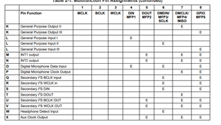
DIN / MFP4 (pin 4) is not used;
SCLK / MFP3 (pin 8) is used as a PCM CLK 8kHz input from a modem.
MISO / MFP4 (pin 11) is used for PCM DATA output to a modem.
GPIO / MFP5 (pin 32) is used for PCM CLK 2.048MHz output to a modem.
Basically, pins 8, 11 and 32 route audio to a modem's PCM input voice channel and I need this.
Question 1: As per document SLOS602A–SEPTEMBER 2008, P0_R81 (ADC channel setup):
D5–D4 R/W 00 Digital Microphone Input Configuration
00: GPIO serves as Digital Microphone Input
01: SCLK serves as Digital Microphone Input
10: DIN serves as Digital Microphone Input
11: Reserved. Do not use
D3 R/W 0 Left Channel Digital Microphone Power Control
0: Left Channel ADC not configured for Digital Microphone
1: Left Channel ADC configured for Digital Microphone
D2 R/W 0 Right Channel Digital Microphone Power Control
0: Right Channel ADC not configured for Digital Microphone
1: Right Channel ADC configured for Digital Microphone
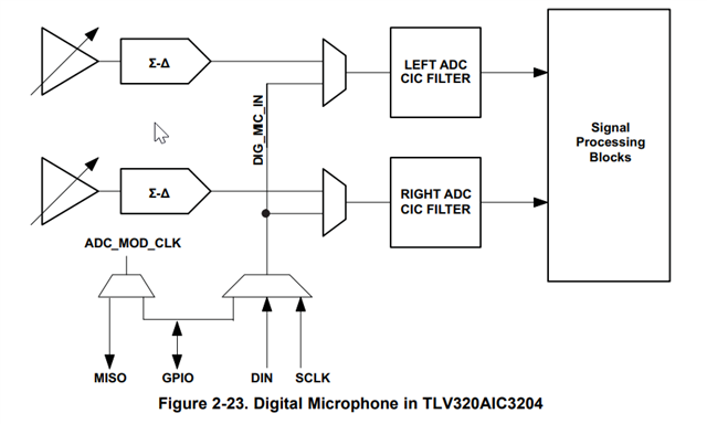
I presume that I need to select only ONE of the above options? So if I want to select right ADC as mic input, then I wouldn't need to configure D5-D4 so how do I configure these registers? Do I set them to '11' eventhough it says "Reserved. Do not use"? Basically, what I get from this is that a digital mic can stream its PDM data to 5 different digital inputs?
Question 2: As per the table in question 1, if I decide to use "left channel" as digital input, I presume that it blocks the entire left channel (pins 13, 15 and 20) for digital microphone inputs? If this is the case, then perhaps I should experiment with the right channel since it is not used? Therefore, I would set P0_R81 to 0bx10001xx?
Question 3: Again as per SLOS602A–SEPTEMBER 2008 page 25, figure 5.2 "Analog routing diagram", if I use INx_R for the digital microphone input, before going into the ADC, it goes into the Mic PGA. Since this is a digital mic, I presume I will not need the Mic PGA so then I would simply set P1_R59/60 to Left/Right MICPGA is set to 0dB? This would then make that I don't need to configure P1_R52/R54/R55/R57 either?
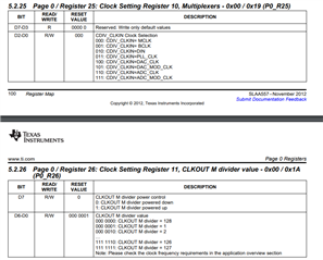
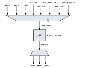
Question 4: Once I have the digital microphone input configured (e.g. IN1_R pin 14), I guess I don't have the choice but to sacrifice either pin 8, 11 or 32 for the microphone clock? Or is there another pin I can use to time the data? For instance, on my existing circuit, pin 1 MCLK has a 3.072MHz clock going to it coming from a microcontroller. Can I use that for the clock for microphone clocking since this is the base CODEC clock, therefore, everything should be synched off that clock?
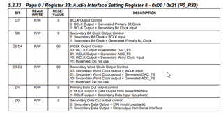
Question 5: Once I confirm that microphone has proper clocking and sends its data to the CODEC input, how can I route that I2S audio to the DOUT / MFP2 (pin5) or SEC_DOUT / MISO_MFP4 (pin 11)?
Hopefully this all makes sense!
Thanks!
Benoit


 .
.
