TPA3255: TPA3255 Simple SE input circuit for BTL

Part Number: TPA3255

Tool/software:

Interested in making the simplest possible SE input circuit for a BTL configurated TPA3255, to be used from 60Hz up, with an 6dB input filter.

1: Can input_B be connected directly to ground instead of a capacitor of the same value as input_D as normally used?

2: Except for half gain, will there be any performance or sound degradation when going SE like in the sketch below? Input_C and input_D via cap if necessary?

3: If BTL is not possible, we could use the chip SE connected.

Looking forward to your reply.

Lars Soderquist
Racer Direkt AB
Sweden
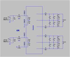
  • hi Lars

    a cap should be necessary for input. please use below connection method.

    as the input become SE, i am afraid that the unbalance might lead to the thd be worse.

    thanks

    jesse

  • Thanks for immediate answer.


    After thinking it through I realize that the high sensitivity drivers involved does not need BTL:

    If going SE with 8ohm speaker I have redesigned the filter to have characteristics without overshoot.

    Three questions:

    1: To form a 60Hz HP filter on the input of ALT.2 , is it OK to shunt INPUT_A with a resistor directly to ground?

    2:In ALT.1 is it OK to shunt the secondary winding directly to ground?

    3: As channel B will not be used, can INPUT_B be grounded directly without capacitor?

    4: About OUTPUT_B should the output be terminated? Diodes or resistor?

    See attachment.

    Thanks in advance!

    Lars Soderquist
    Racer Direkt AB
    Sweden


  • Hi Lars,

    The inputs should always have a capacitor and not get shunted to ground regardless of if they will be used or not. For a 1xBTL and 1xSE setup like you are describing, you should follow the 2.1 setup described in the datasheet which uses 2x SE and 1xBTL and then load channel B with a resistor (maybe 8 or 16 ohms). This means all 4 input pins will have the input capacitors and for the 60Hz HPF a filter should be added before the input cap. 

    However, I would recommend that you switch to a 2xBTL configuration instead of a 1xBTL, 1xSE, 1xunloaded configuration. With a 2xBTL configuration, your efficiency will be better, thermals would be a bit easier to manage and you wouldn't need large AC coupling capacitors on the output. This app note gives a simple circuit for converting single ended inputs to differential.

    Source -> HPF -> input cap -> input pin

    Regards,

    Ramsey

  • Hi Ramsey,

    Thanks for you answer, but if I am not mistaken, it contradicts to what Hao said a few years ago:

    TI__Mastermind 19080 points

    " Hi Alex,

    Theoretically, you can remove this capacitor as long as the input signal is guaranteed as AC signals. However, to protect the device, inductor, and also the speaker from burn-out by DC signal, the AC coupling input capacitor is necessary here. So please keep it in your design.

    Regards,

    Hao"

    As I have an input capacitor before the shunt resistor, this should then be possible, if we assume Hao to be correct. The reason for going SE is twofold, as I don´t need very much power and also want to have the driver capacitor coupled output to protect the driver.

    Cheers,

    Lars Soderquist
    Racer Direkt AB
    Sweden

  • I tend to complicate things a little to much. Just remembered the DSP for subbass is balanced out, so I will go directly to the input caps without any alterations of the original BTL configuration.


    About the SE part I decided to add a small buffer with the A_input capacitor forming a HP filter.

    The question that still remains is out and input of the B-channel that will be permanently disabled. It would be very conveniant if the output filter could be removed. Will it be doable?

    https://www.diyaudio.com/community/attachments/1736507124551-png.1405660/

    Cheers,

    Lars Soderquist
    Racer Direkt AB
    Sweden

  • Hi Lars,

    One of the reasons I suggest not adding in the shunt resistor after the cap is due to the internal DC bias the pins have. Adding a shunt here will draw current continuously and has not been validated or tested on the device. In theory a sufficiently large resistor will not have a noticeable impact, but in general it is better to do your filtering before the cap or use the input impedance of the amp as the resistor for a low pas filter.

    For input channel B, you should still have the cap on the input pin to ground. On the output side, you will need to keep the bootstrap capacitor, but the LC filter could be removed.

    Best regards,

    Ramsey

  • Hi Ramsey, this seems to be all I needed to know. Adding the buffer will solve the input problem. About the unused channel, input grounding via capacitor and removing the LC network and no termination is OK? Sounds easy enough.