This thread has been locked.

If you have a related question, please click the "Ask a related question" button in the top right corner. The newly created question will be automatically linked to this question.

TAS2563: TAS2563 (other methods than baremetal driver )

Part Number: TAS2563
Other Parts Discussed in Thread: CC1352P, PCM1822

Tool/software:

Hi 

I read the discussion of the baremetal driver kit for tas2563.  ( https://e2e.ti.com/support/audio-group/audio/f/audio-forum/1349736/tas2563-bare-metal-driver/5161027?tisearch=e2e-sitesearch&keymatch=tas2563%20baremetal#5161027 )

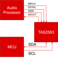
However, our system do not have any drivers or driver-level software. Our systems only have the simplest MCU (about 40pins),  CC1352P, echo canceller, PCM1822 (for the analog beep sound from the MCU) and TAS 2563. 

(1) Is there any other way for us to configure TAS2563, tune EQ and set the parameters for speaker protection ?

(2) With such a simple architecture, could we write our parameters and information directly to TAS2563 and let TAS2563 memorized?

(3) Continued (2), if we could not do that, what else do we need to add? (e.g. flash? or something?)

Thanks.

  • I have no idea of the meaning of other way? Would you be so kind to offer more details?

    Once the program and config are written into the tas2563, if the tas2563 do not hardware shutdown. The program and config will still inside tas2563, even if it is in software shutdown mode.

  • I put the TAS2563 directly into my system, and there are no drivers in my system. Is there any way I could adjust the parameters (i.e., EQ and so on) and directly let TAS2563 remember my adjusted parameters?


    To be more precise, I have designed a system on my PCB boards with MCU, CC1352P, echo canceller, PCM1822 and TAS 2563 (because it involves confidentiality, I do not know how to just share the system architecture with you.) Is there any other way for me to directly let TAS 2563 remember my newly adjusted parameters after adjusting the speaker parameters and EQs without baremetal drivers?

    Thanks.

  • Hi team,

    Could you help reply to Paul soon?

    It looks Shenghao will be back in next week due to CNY holidays.

    Thanks! 

  • Hi Guy
    Kindly apply for the PPC3 tool for tas2563. In that tool, there's a feature to generate the header file for the dsp setting and filter setting.

    PPC3 tools link: PUREPATHCONSOLE Application software & framework | TI.com

    The header files are like following:

    dsp fw

    2210.program_0_Tuning Mode.h

    filter ceof(enable echo ref are set in coef)

    configuration_0_music_TuningMode_DEV_A_COEFF.h

    Pls integrate following code mentioned in the header file's comments into your system.

    transmit_registers() is the function to convert the array into i2c commands.

    What you do is to implement the delay() and i2c_write in your system.

    extern int i2c_write(unsigned char *data, int n);
    // Externally implemented function that delays execution by n milliseconds
    extern int delay(int n);
    // Example implementation.  Call like:
    //     transmit_registers(registers, sizeof(registers)/sizeof(registers[0]));
    void transmit_registers(cfg_reg *r, int n)
    {
        int i = 0;
        while (i < n) {
            switch (r[i].command) {
            case CFG_META_SWITCH:
                // Used in legacy applications.  Ignored here.
                break;
            case CFG_META_DELAY:
                delay(r[i].param);
                break;
            case CFG_META_BURST:
                i2c_write((unsigned char *)&r[i+1], r[i].param);
                i +=  (r[i].param / 2) + 1;
                break;
            default:
                i2c_write((unsigned char *)&r[i], 1);
                break;
            }
            i++;
        }
    }

  • Hi Shenghao,

       I don't quite understand what you mean.

       Where should I put the .h files in my system? In which part of the hardware? 
       Who is responsible for configuring TAS2563?  (MCU?  CC1352?  Echo canceller? or TAS 2563 itself?)

       Thanks.


    Best Regards,

    Paul Lai

  • Hi Guy,

    The guideline and reference code.

    7585.Guideline for integrated SmartAMP baremetal driver & fct.pdf

    https://e2e.ti.com/cfs-file/__key/communityserver-discussions-components-files/6/mono_2D00_code.7z

  • Hi Shenghao,

        Thanks for sharing.
        However, if the MCU I use has limited space, is there any other way I could solve this?

        In addition, there are Echo canceller, CC1352 and other ICs in front of my TAS2563. The TAS2563 is not directly controlled by the MCU. Could I also directly put the header files into the MCU's code? If not, where do you recommend I put it?

        Thanks.

  • As to the limited space, you can put the program and cfg array into the NV part, you will optimize this per your system.

    You must put the header file into the MCU code, it must be compiled into image.

    I do not fully understand "The TAS2563 is not directly controlled by the MCU". Which device on earth issues the i2c command to TAS2563?

    You can only keep prog and conf0 array and remove calibration array, and remove calibration related array to reduce the space consumption. One more thing, if you want to enable echo ref signal, pls use PPC3 to enable it and upgrade the conf array first.

  • Hi Shenghao,

        I use a audio processor from Microsemi to control the TAS2563. Do I need to use the MCU to control the TAS2563 instead?

        Thanks.

  • Which device issue the i2c commands to tas2563, audio processor or Microsemi? In other word, which device control the i2c bus connected to TAS2563, , audio processor or Microsemi?

  • Hi Shenghao,

        Microsemi.
        Do you recommend connecting the TAS2563's I2C to the MCU (Renesas)?  

  • Yes, to MCU.

  • Hi Shenghao,

         Which pins of the TAS2563 should be connected to the MCU? 

         Besides, If I still need the echo cancellation (function) of the echo canceller (Microsemi), how should the entire system be connected?

  • I will involve the hardware guy to support you.

  • Hi Shenghao,

        I found two pins from the MCU for the I2C of the TAS2563 (SCL_SELZ and SDA_MOSI).

  • Let's wait for hardware expert to support you. 

  • Hi Paul,

    It seems you me you have some kind of audio processor to feed audio data into TAS2563, and also for some other functions such as echo cancellation, etc.
    In that case I think your system would looks something like this:

    Note all the signal names are based on TAS2563 perspective.
    The control signals, I2C, come from MCU.
    The audio data, I2S/TDM, is interfaced with the audio processor, which is not the same as MCU.
    Something you must consider is that since MCU is not controlling SBCLK and FSYNC clocks, these clocks must be enabled all the time. If the TAS2563 is enabled (through I2C) while SBCLK and FSYNC are not present, it will shut down automatically due to clock error.

    Best regards,
    -Ivan Salazar
    Applications Engineer

  • Hi Ivan,

        Thanks for your sharing.  

        My design has been changed to resemble your illustration. However, But I still have a question. If I need the echo cancellation function of the audio processor, what should I do?  Could I connect the SDOUT of the TAS2563 to the input of the audio processor, and then let the audio processor provide the signal to the TAS2563?


         In addition, if you want to eliminate the echo, should the digital MEMS microphone signal line be connected to the TAS2563 or the audio processor?

         Thanks.

  • Hi Paul,

    Yes, SDOUT from TAS2563 should connect to input of the audio processor, then the processor can use the echo-reference data from TAS2563 and the playback data for the echo cancellation function.
    The audio data from playback should come from audio processor into TAS2563.
    TAS2563 is able to receive PDM mic signals, however this is only for recording purposes (usable if the processor doesn't have PDM interface), there's no echo-cancellation algorithm internal to TAS2563.

    Best regards,
    -Ivan Salazar
    Applications Engineer

  • Hi Ivan,

        It seems that it is feasible for me to connect the PDM interface microphone to the TAS2563, then send the echo reference signal to the audio processor through the SDOUT1 pin (of the TAS2563) for the echo cancellation processing. After that, the audio processor send the processed signal back to the TAS2563 and let the speaker output the processed signal? Is this right?

       Besides, If I want to control the EQ of the PDM interface microphone through TAS2563, is the above path also feasible?  Thanks.


  • Hi Paul,

    The PDM recording feature on TAS2563 does not include any processing, so EQ is not applicable for PDM data.
    If you're using PDM interface on TAS2563 you must also send the PDM recording data through SDOUT1, along with echo reference.

    Best regards,
    -Ivan Salazar
    Applications Engineer

  • Hi Ivan,

        Does "I must also send the PDM recording data through SDOUT1" mean that I need to do something extra? Does this mean that I could follow Section 4 of "Application note: TAS2563 PDM Microphone Interface and Echo Reference"?

        Besides, according to the same documents, I'm not sure if I could do the smart amplifier setting and PDM settings separately? Or could I only choose one of the two in the same project?

       Moreover,  the audio processor are only MCLK and LRCLK. Is the following connection method appropriate?

                  MCLK (I2S) <--> SBCLK1

                  LRCLK (I2S) <-> FSYNC

        Thanks.

  • Hi Paul,

    • Yes, you can follow as described in the app note.
    • Once you select a mode in PPC3, either PDM or smart amp only, that is the configuration you'll use for any snapshot in that configuration. You may use two different bin files for two different configurations, one with PDM and one without it, you'll have to reinitialize the device with the corresponding bin file for each case (not sure how complicated is that from the driver/software perspective).
    • SBCLK is direct multiple of FSYNC, eg. for 48kHz sampling rate, 2 channels and 32-bit word length SBCLK must be 3.072MHz. As long as your MCLK and LRCLK follow this it should be OK to use as you describe.

    Best regards,
    -Ivan Salazar
    Applications Engineer

  • Hi Ivan,

        Thanks. Is there anything else I need to pay attention to?

    Hi Shenghao,

          As Ivan mentioned above, if I want to use two different bin files for two different configurations, one with PDM and one with smart amplifier. After that, I will initialize the device twice with the corresponding bin file for each case. Will this be complicated? Thanks.

  • Hi Paul,

    I think we've covered most of it.

    Best regards,
    -Ivan Salazar
    Applications Engineer

  • Hi Paul

    You can make only one dsp bin file with 2 configs. Our PPC3 tool support such application.

    Page 40 ~ page 45 in the PowerPoint 演示文稿 introduced how to switch different configs and profiles, our dsp bin file supports several configs.