This thread has been locked.

If you have a related question, please click the "Ask a related question" button in the top right corner. The newly created question will be automatically linked to this question.

TAS2780: Support for classic stereo I2S mode

Part Number: TAS2780
Other Parts Discussed in Thread: TAS2770

Tool/software:

Hello,

         I have a custom design where an MCU drives TAS2780. The audio data is hardcoded in the firmware ( this is for test purpose). The SAI settings are as below

Sampling rate 48k

Bitwidth: 16

Channel/mode : Stereo

Attached are the waveforms of I2S CLK, DATA and FSYNC. Can you check if TAS2780 can accept this format ?

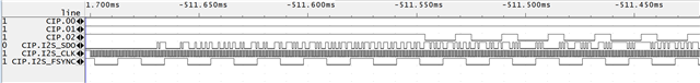
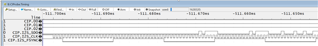
I also decoded and plotted the complete I2S data & i could see a sine wave as I had expected. 

Coming to the TAS side of things, TAS seems to be completely silent. Below are the custom settings that i had applied to TAS2780

0x00, 0x00, //access page 0

0x0A, 0x32, //Stereo down mix, word slot and time slot 16/32 bits.

0x60, 0x00, //sclk and fsync ratio :16

0x08, 0x19 //disable auto rate detection

Attached is the full TAS2780 initialization code that I did.

TAS2780_init.h

My questions are:

1. Will tas2780 accept classic I2S stereo stream? FYI: I2C address of the device is 0x70

2. What are the additional settings needed for TAS2780 to accept the above datastream

3. Is my initialization sequence correct ? Each row in the array ( of TAS2780_init.h) is sent to TAS2780 as a separate I2S write transaction. First entry in the row is register address and last entry in the row is data.  

  • After further debugging I found issues with my I2C driver. The initialization sequence sent to TAS2780 was wrong. I fixed it and now, I can see the dats in i2C line matches with expectation. 

    in TAS2770 thread in E2E, came across this statement : " I2S must be present before the device is enabled" .  Is it true for TAS2280 too ? I did that in my setup. I sent  tas2780CustomConfig after I2S stream is started. 

    To debug, i read back all INT_LTCH* registers. I get "Interrupt due to TDM clock error" & "TDM clock error type = Invalid SBCLK ratio or sampling rate ,TDM clock error type = Sampling rate changed on the fly" error . INT_LTCH0=0x04 & INT_LTCH4 =0x06 . other registers all read 0 . i get the same error when i send all the configuration data before or during the I2S stream. 

    I see that my bit clock is 1.5MHz (based on logic analyzer output). Can this be the cause of problem ?

    Below is my custom config that i send to TAS2780 after setting the power mode 0 option. 

    const uint8_t tas2780CustomConfig[]=

    {

    0x00, 0x00, //access page 0

    0x08, 0x19, //disable auto rate detection

    0x0A, 0x30, //Stereo down mix, word slot and time slot 16/16 bits.

    0x60, (2<<2), //sclk and fsync ratio :32

    0x0C, 0x20 // set Right channel slot to 2

    };


    My i2S settings are very similar to this post

  • Hi Syam,

    FSYNC and BCLK must be running before writing to register 0x02, that is correct for TAS2780 as well.

    Why disabling auto rate detection? You may test with this feature enabled.
    Standard I2S format is supported, that should be no problem.

    Do you know if the frequency of the FSYNC and BCLK in your system is too unstable? That may be detected as a clock error.

    Best regards,
    -Ivan Salazar
    Applications Engineer

  • Greetings Ivan,

                            As you had mentioned, I disabled auto rate detection & set the mode control after I started the i2S stream. Initially, i was presented with a crackle from the speaker. I know my BCLK waves are pathetic with lot of ringing. I disabled auto rate detection and attempted again. This time, speaker gave out sound along with clipping. I went ahead and reduced the AMP_LEVEL setting to minimum. The speaker started to work even better, with audio having minimal clipping / break. I reduced the drive strength of SAI pins on the MCU. That made speaker sound even better. I will add series termination to make bclk and fsync more smooth. 

    I am still presented with following interrupts

    INT_LTCH0: 0x04

    INT_LTH1: 0x02     //inconsequential I suppose. 

    INT_LTH1_0: 0x19 //Inconsequential i suppose.

    INT_LTH4: 0x06

    I need to fight these out now!

    For now, I can play the sound and validate that PCB is up.  It will be great if the sequence of mode control register write is mentioned in the datasheet. 

    Can I keep this thread open until I figure out on how to address the clock's issue ? 

  • I reduced the drive strength on my SAI pins & now I can see cleaner edges for all SAI signals. I can play sound with manual or auto rate detection. I still have the INT_LTH* interrupts to clean up. I will post the observations in another thread.