This thread has been locked.

If you have a related question, please click the "Ask a related question" button in the top right corner. The newly created question will be automatically linked to this question.

TLV320AIC3254EVM-K: Recording Configuration Not Showing IN3 Option

Part Number: TLV320AIC3254EVM-K

Tool/software:

Hi. At the moment, I am trying a simple onboard microphone to digital output configuration for this evaluation module (TLV320AIC3254EVM-K). I have been following a very helpful resource from another post on this forum.

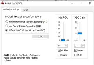
However, I keep running into an issue. In the AIC3254EVM-U CS software, the recording configuration I need is not showing up. I need to use IN3 but I only get the option of High Performance Stereo Recording (IN1) and Low Power Stereo Recording (IN1). This is shown in a photo below.

From the user manual, I have all of the default jumpers installed. Of particular relevance, I have the following jumper configuration: W1: 2-3, W2/W3/W5/W6/W7: installed, W8: 2-3, W-4 removed.

I have tried it on Firmware: USB-AudioEVM Version 3.04 as well as on USB-miniEVM Version 2.03. In both cases, IN3 is not an available option:

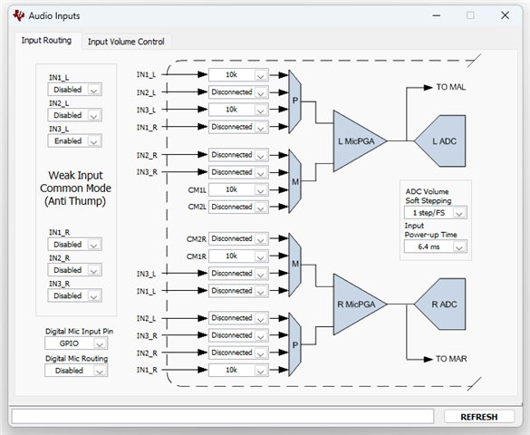
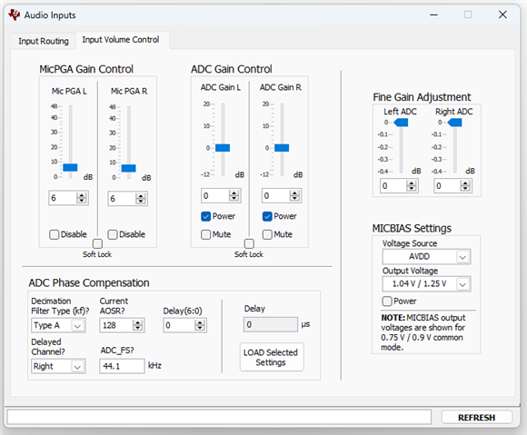
In Analog Settings > Audio Inputs, my settings look like this:

Any help would be greatly appreciated. Thank you.

  • Hi Jack,

    Sorry for the inconvenience, the presets were simply written with only IN1L in mind. There are two options you can do

    1) If you click the "Script" tab next to the Recording Presets, you will see the full script used to run that particular preset. You can copy this into the command line interface (back on the main GUI window) and tweak the registers to match your needs, so for instance connecting IN3L instead of IN1L.

    2) Open the command line interface and click "record." Now all I2C writes done in the GUI are captured here for reference. You can run the recording preset to enable 1L recording, go back to the Input Routing window and click "refresh". Then make the changes desired in the GUI. All of these changes are captured in the command line interface window so that you can generate your own script based on your needs.

    Best regards,
    Jeff McPherson

  • Hi Jeff,

    Thank you very much for your response.

    I have followed your instructions and I was able to record the changes I made, which after executing the command buffer, now remain there upon refreshing.

    When these changes are made, is the graphic in Typical Configurations > Recording > Typical Recording Configurations supposed to update to show these new changes (such as the availability of IN3)? Or are these just default presets with a few customizable controls, and everything else should be done in scripts? I suppose I am confused since it seems a previous version of the software, from tutorials and forum posts I've followed, seem to have an option for "Differential On-Board Microphone (IN3)" there. (A photo is attached below for clarity). Perhaps this was just a preset that was removed?

    Just to be clear, this is the screen that contains Typical Recording Configurations I'm referring to:

    In summary:
    I suppose what I am ultimately asking is: is what is shown in "Audio Inputs" how the system is actually configured (disregarding Typical Configurations > Recording)? As long as it is correctly configured (and executed) there, the eval. board is configured correctly?

    Also, if there is an updated link to example scripts for this board (such as the answer provided at this link -- however, this one says I don't have access), that would be greatly appreciated.

    Thank you again,
    Jack

  • Hi Jack,

    I'm not sure why it was removed. But your understanding is right, as long as the Audio Inputs tab is correct (after refresh) it'll be configured correctly all else being equal.

    I'm not sure why you can't get the scripts shared on the link you provided. I'm attaching them here for you, however they are pretty identical to the preset scripts. Just in case you want the reference I'll attach them below for you.

    AIC32x4_MIC_SCRIPTS (1).zip

    Best regards,
    Jeff McPherson

  • Hi Jeff,

    Thank you so much for all of your help! I've got it working now.

    I've compiled / written a script that uses the differential onboard microphone (assuming the jumpers are properly connected, as specified in the TLV320AIC3254EVM-K user guide) and I'm able to record it into Audacity. I am attaching it here in case others run into the same problem and want a plug-and-play script for quick testing using the onboard microphone.

    This script can be run from the Command-line Interface of the AIC3254 CS software, and after running it, you can select the evaluation board (in my case named "USB-miniEVM") as an input device in your audio software. Then you can start recording with the onboard microphone.

    Best,
    Jack

    # ---------------------------------------------
    # Low Power Stereo Recording Using On-Board Microphone 
    # Tested on a TLV320AIC3254EVM-K board
    # IN3L/R with MICBIAS applied
    # ---------------------------------------------
    # PowerTune mode PTM_R1 is used for low power
    # consumption. 
    
    # Software Reset
    # ---------------------------------------------
    # Select Page 0
    w 30 00 00
    # Initialize the device through software reset
    w 30 01 01
    
    # Clock Settings
    # ---------------------------------------------
    # The codec receives: MCLK = 11.2896 MHz,
    # BLCK = 2.8224 MHz, WCLK = 44.1 kHz
    # Select Page 0
    w 30 00 00
    #
    # NADC = 1, MADC = 4
    w 30 12 81 84
    #
    # AOSR = 64
    w 30 14 40
    
    # Signal Processing Settings
    # ---------------------------------------------
    # Select Page 0
    w 30 00 00
    #
    # Set the ADC Mode to PRB_P7
    w 30 3d 07
    
    # Configure Power Supplies
    # ---------------------------------------------
    # Select Page 1
    w 30 00 01
    #
    # Power up AVDD LDO
    w 30 02 A9
    #
    # Disable weak AVDD in presence of external
    # AVDD supply
    w 30 01 08
    #
    # Enable Master Analog Power Control
    # Power up AVDD LDO
    w 30 02 A1
    #
    # Set the input power-up time to 3.1ms (for ADC)
    w 30 47 32
    #
    # Set the REF charging time to 40ms
    w 30 7b 01
    
    # Recording Setup
    # ---------------------------------------------
    # Select Page 1
    w 30 00 01
    #
    # IN3L is routed to Left MICPGA with 10k resistance
    w 30 34 04
    #
    # CM is routed to Left MICPGA via CM1L with 10k resistance
    w 30 36 40
    #
    # IN3R is routed to Right MICPGA with 10k resistance
    w 30 37 04
    #
    # IN3L is routed to Right MICPGA with 10k resistance
    w 30 39 04
    #
    # Left MICPGA Volume Control = unmuted, 24dB
    w 30 3B 30
    #
    # Unmute Right MICPGA, Gain selection of 6dB to make channel gain 0dB
    # Register of 6dB with input impedance of 20K => Channel Gain of 0dB
    w 30 3C 0c
    #
    # MICBIAS powered up, using power supply voltage, MICBIAS voltage from AVDD
    w 30 33 70
    #
    # Select Page 0
    w 30 00 00
    #
    # Power up LADC/RADC
    w 30 51 c0
    #
    # Unmute LADC/RADC
    w 30 52 00