This thread has been locked.

If you have a related question, please click the "Ask a related question" button in the top right corner. The newly created question will be automatically linked to this question.

TPA3221: TPA3221 Short circuit testing issue

Part Number: TPA3221
Other Parts Discussed in Thread: TPA3223, TPA3251

Tool/software:

Hi 

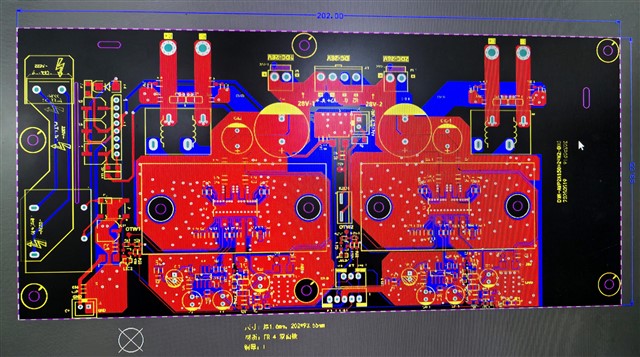
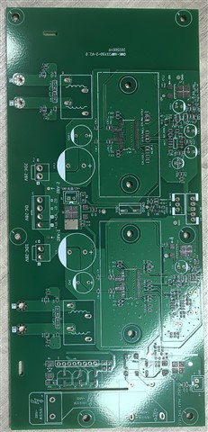
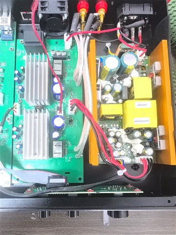
Customer designed a 2 * 200W (2 Ω load) digital amplifier board, using TI's TPA3221 chip and PBTL mode.
This is a PCB picture of the amplifier board and power board.
Power supply: Adopting a 350W switching power supply, with a main voltage of 28.5V, it can provide a current of 11A.
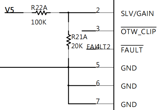
Attachment: Schematic diagram 

Issue:
1. When conducting short-circuit testing on the output, it is easy to damage IC, mainly the PVDD pin damage.
2. It is easy to damage the IC when inputting large audio signals. Currently, the issue has been resolved by optimizing the ground.
Please analyze the reasons and provide solutions. (customer requirement: Each channel of the power amplifier needs to be connected in parallel with 3 8 ohm 50W speakers, with a load impedance of 2.7 Ω 150W. Is TPA3221 suitable? Do we need to replace TPA3223 or TPA3251 with PBTL mode? We need to improve protection functions such as short circuit, overheating, and overcurrent.)
thank you!

DMK-AMP2X150-2-V2.0-20250519.pdf

  • hi, 

    sorry for confusing, i will reply you within this week as some info need to check inside of team.

    thx

    jesse

  • Hi Jesse,

    Out for GND short circuit test, IC protection. OUT+ OUT- Short circuit, damaged IC.

    Customer current issue is the load short circuit test, which did not activate the protection mechanism and damaged the IC. There are two requirements.
    1. Does the IC have out+ out- load short circuit protection function.
    2. If there is no protection function, can an external protection circuit be recommended.

  • hi, 

    pls let me confirm several points:

    1.can you check the pvdd voltage when short happen?

    2.your 2x200w is 10% thd or 1%thd. as you can see in DS, the 200w/2ohm is very close to this device's limitation. 

    3.about the layout, you need to put 0.1uF cap as close as to the pvdd pin. pls confirm this point. the heat sink seems block the cap be close to pvdd pin.

    4.what is your inductor's Isat? you need at least around 15A. in my understanding ,20A is better.

    5.all GND has to be connected together. pls also confirm this.

    thx

    jesse

  • Hi Jesse,

    1. The maximum voltage during a short circuit is 31.67V
    2. The power is 2 * 180W, with a total harmonic distortion of 10%
    3.0.1uf is located close to the PVDD foot
    4. The rated current of the inductor is 15A
    5. All GNDs are connected together

  • hi, 

    1.can you kindly test your pvdd waveform when playing music? what is its peak voltage it can get.

    2.about the gain of you amp, i find that the resistor is 75k and 15k, this is not what we recommend. do you have any purpose setting like that?

  • Hi

    1. The maximum peak voltage is 32.33V.
    2. We have used the 100K and 20K resistors recommended in the manual for 24dB gain adjustment. In PTBL mode, the load is 2 ohms, and the false load resistor has a power of 20W. If the short circuit continues, out+ out- short will damage IC. The short circuit duration is within 1 second, and out± to GND short protection is instantly effective. Currently, the problem only short circuit between out+ out- protection being ineffective.

  • hi, 

    let me discuss this issue internally, and reply you this week.

    thx

    jesse

  • hi, 

    can you kindly help check the current before LC fitler when S2G and short between P and N.

    we haven't encounter this kind of problem, the oc protection should be able to b available for both situation.

    you can decrease the pvdd voltage to perform this testing first to avoid IC damage.

    thx

    jesse