


Other Parts Discussed in Thread: TAS6424, LSF0108
Tool/software:
Dear Ti master,
Our project is using tas6424-q1.
Our problem is that the waveform of mclk is not normal. There is an offset.
How can we fix this problem?

This waveform is a mclk waveform. An offset occurs.
Below is our schematic.
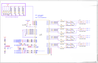
Can mclk cause a "Clock fault detected" fault? We are currently experiencing a "Clock fault detected" fault interrupt.
I would appreciate your help.


