Tool/software:
Hi everyone,
We’re using the TLV320AIC3104 (TLV320AIC3104IRHBR) audio codec on our custom board, and we’re currently facing an issue with getting audio output through Line-Out.
Problem:
-
When we try to play audio on our custom board, there is no output from Line-Out or headphone out.
-
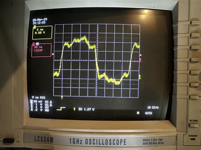
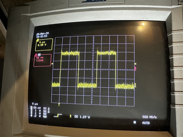
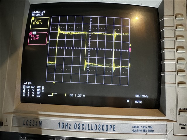
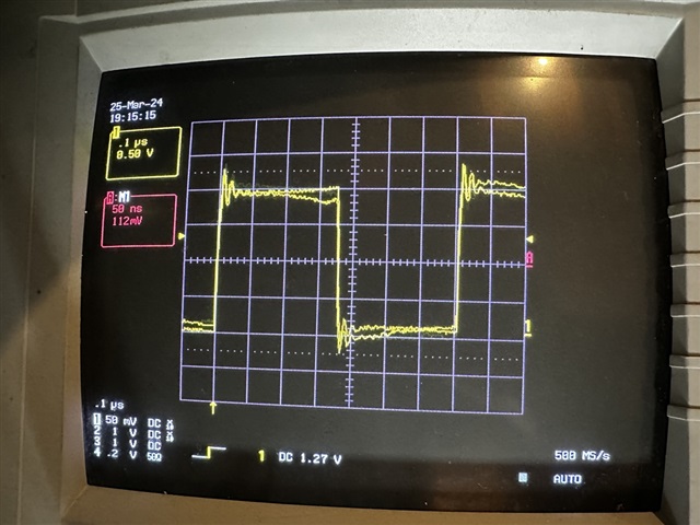
In some cases, we hear very noisy/distorted sound.
-
However, when testing the same audio settings on the official EVM (TLV320AIC3104EVM-K) using the AIC310x EVM GUI tool, everything works as expected.
EVM Test Results:
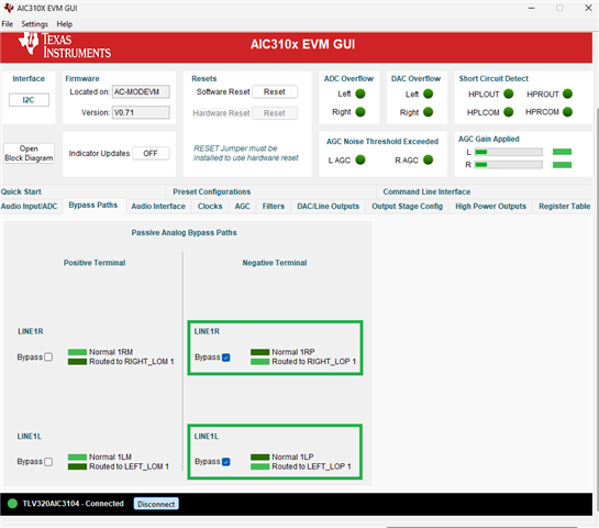
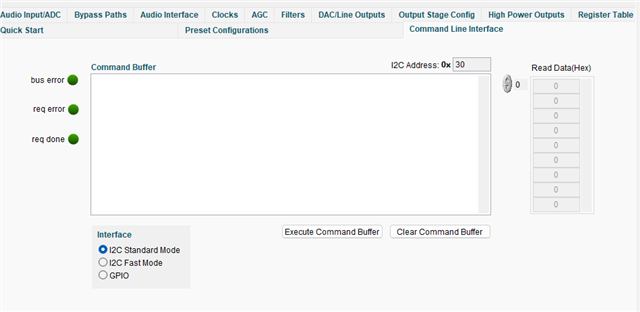
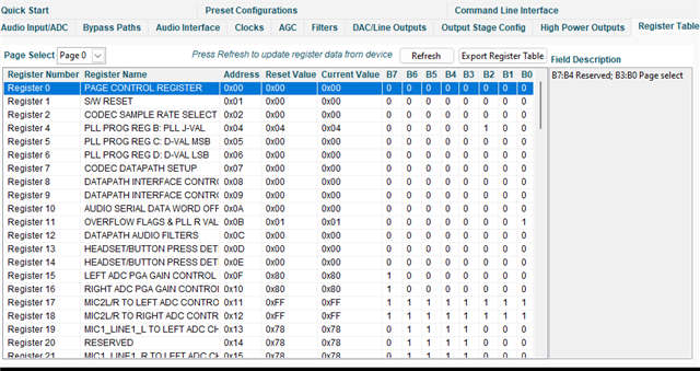
We tested two different preset configurations (as shown in the screenshot) from AIC310x EVM GUI tool, and were able to get audio output on headphones and line out based on the settings. To replicate the same behaviour on custom board, we copied the I2C command execution from the Command Line Interface of the AIC310x EVM GUI tool. 
Here is execution logs for each preset configuration test.
-
Preset Configuration 1 : Stereo Playback to Capless Headphone Outputs,
These I2C commands produced clean audio output on the EVM:
i i2cfast
w 30 07 8A
w 30 66 A0
w 30 29 02
w 30 2B 00
w 30 0E C0
w 30 25 E0
w 30 26 10
w 30 2F 80
w 30 40 80
w 30 41 0D
w 30 33 0D - Preset Configuration 2: Stereo Playback to Lineouts,
Also worked on EVM with the following configuration:
i i2cfast
w 30 07 8A
w 30 66 A0
w 30 25 C0
w 30 29 02
w 30 2B 00
w 30 52 80
w 30 5C 80
w 30 4B 80
w 30 4E 80
w 30 56 09
w 30 5D 09
w 30 4F 09
Issue on Custom Board:
-
We applied both sets of register configurations to our custom hardware.
-
Unfortunately, neither configuration provides clean audio or any line-out signal on the custom board.
-
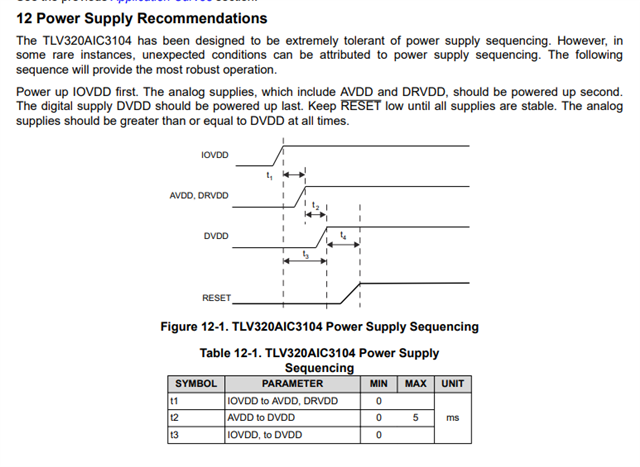
Power rails and I2C communication appear normal.
-
MCLK and other clocks seem to be present and stable.
Our Goal:
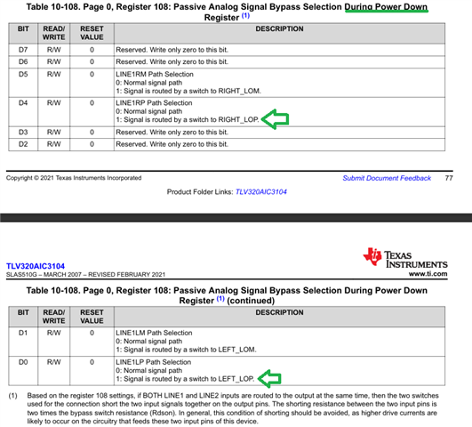
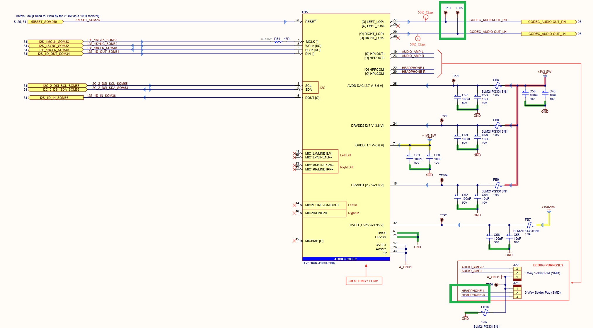
We’re trying to get clean audio output through the Line-Out channels (LEFT_LOP+ / RIGHT_LOP+), as shown in the screenshot, on our custom board using the TLV320AIC3104 codec.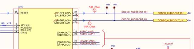
Request:
Has anyone had the same issue when moving from the EVM to a custom board?
We’d really appreciate any help or suggestions especially if there are any changes, missing settings (like using amixer or RAW I2C commands), or setup steps we might have missed.
Thanks in advance for your support!