This thread has been locked.

If you have a related question, please click the "Ask a related question" button in the top right corner. The newly created question will be automatically linked to this question.

TLV320AIC3100 DAC Flags & ALSA SoC Driver

Other Parts Discussed in Thread: AM1808, TLV320AIC3100, TLV320AIC23, TLV320AIC26, AM3352

Hi,

I have a design centered around an AM1808 which is laid out using McASP0 to interface to a TLV320AIC3100. Up to this point I've been able to use the existing davinci-evm.c  and davinci-mcasp.c SoC modules with slight modifications to get data out of the AM1808 using aplay to playback a wave file. I've based my own board file off of the existing board-da850-evm.c file which registers the davinci-evm.c, davinci-mcasp.c and tlv320aic3x.c modules such that aplay sees a sound card. I've been modifying the tlv320aic3x.c driver to control my tlv320aic3100 and have come to a  point where I believe I have all registers set appropriately for playback out of both the speaker and headphone outputs. I haven't gotten to the ADC side of things yet as I'm trying to get DAC outputs going first. 

The issue I'm having with the codec setup is that the DAC flag register (page 0 register 37) only shows the Left channel DAC powered on while all the control registers indicate the left and right channel DACs, speaker amp driver and the right and left channel headphone drivers are all powered on.

CLASSD_SPEAKER_AMP(P1/R32): 0x86   Bit 7 indicates class-D speaker amp powered up
DAC_CHN_REG(P0/R63): 0xd4                     Bits  6 and 8 indicate right and left DACs powered up
HEADPHONE_DRIVER(P1/R31): 0xd4        Bits 6 and 7 indicate right and left head phone drivers powered up
DAC_FLAG_1(P0/R37): 0x80                         Only bit 7 is set indicating left DAC is powered up.

I'm not sure if I'm missing something or not but I'm guessing I need to see everything powered up in the DAC flag register before I'll get any audio out. Is this a safe assumption? Is there a sequence of events that needs to take place which isn't outlined in the datasheet that I might need to follow? I am performing both a hard and soft reset when the driver is probed.

Below are all of my register values read back that I've written to in addition to some read only registers. I'm using the codec as a frame and master clock slave. The master clock rate is 24.576MHz, bit clock rate is 1.536MHz and the sampling frequency is 48kHz.

AIC3X_RESET(P0/R1): 0x0
OT_FLAG(P0/R3): 0x2
INTERFACE_SET_REG_1(P0/R27): 0x40
INTERFACE_SET_REG_2(P0/R29): 0x0
CLK_REG_2(P0/R5): 0x81
CLK_REG_3(P0/R6): 0x1
CLK_REG_4(P0/R7): 0x0
CLK_REG_5(P0/R8): 0x0
NADC_CLK_REG(P0/R18): 0x82
MADC_CLK_REG(P0/R19): 0x81
ADC_OSR_REG(P0/R19): 0x20
BCLK_N_VAL(P0/R30): 0x18
DOUT_CTRL(P0/R53): 0x2
ADC_FLAG(P0/R36): 0x80
NDAC_CLK_REG(P0/R11): 0x82
MDAC_CLK_REG(P0/R12): 0x81
DAC_OSR_MSB(P0/R13): 0x0
DAC_OSR_LSB(P0/R14): 0x20
DAC_CHN_REG(P0/R63): 0xd4
DIN_CTL(P0/R54): 0x2
DAC_MUTE_CTRL_REG(P0/R64): 0x0
AIC3100_LDAC_VOL(P0/R65): 0x0
AIC3100_RDAC_VOL(P0/R66): 0x0
DAC_FLAG_1(P0/R37): 0x80
DAC_FLAG_2(P0/R38): 0x80
OVERFLOW_FLAG(P0/R39): 0x0
VOL_MICDECT_ADC(P0/R116): 0x80
VOL_MICDECT_GAIN(P0/R117): 0x0
L_ANLOG_VOL_2_SPL(P1/R38): 0x80
DAC_MIX_CTRL(P1/R35): 0x44
CLASSD_SPEAKER_AMP(P1/R32): 0x86
SPK_DRIVER(P1/R42): 0x14
HEADPHONE_DRIVER(P1/R31): 0xd4
L_ANLOG_VOL_2_HPL(P1/R36): 0x80
R_ANLOG_VOL_2_HPR(P1/R37): 0x80
HPL_DRIVER(P1/R40): 0x36
HPR_DRIVER(P1/R41): 0x36
ADC_PRB_SEL_REG(P0/R61): 0x4
MIC_PGA(P1/R47): 0x0
MIC_GAIN(P1/R48): 0x30
AIC3100_MICBIAS_CTRL(P1/R46): 0x9
ADC_FGA(P0/R82): 0x0

I did see the post "Linux device drivers for AIC31xx/DAC31xx/AIC325x/AIC320x/AIC326x/AIC321x" http://e2e.ti.com/support/data_converters/audio_converters/f/64/t/266169.aspx and cloned the git project but was unable to find any code, specifically in sound/soc/codecs/, that pertained to the 3100.

I also began following the instructions but I seem to be missing "Support Texas Instruments AIC31XXX" and "Support Texas Instruments AIC3XXX platform with I2C" under Device drivers -> Multifunction device drivers in the kernel menuconfig.

Does an ALSA SoC driver currently exist for the TLV320AIC3100?

  • At first glance your setup looks ok. I'll check your settings on an EVM and I'll check driver availability for this codec.

  • I did a little more experimenting and noticed that the value of the DAC flag register mirrored the value of the right analog volume to HPR register (both register number 37 on pages 0 and 1 respectively) as I changed it's value. I took a look at my read and write functions and from what I could tell they appeared to be changing pages as I'd expect them to. I went back and replaced all of my reads and writes with snd_soc_read() and snd_soc_write() and explicit manual page changes before reading and writing. Now I get read values of 0xffffffff from all page 1 registers and even registers 116 and 117 on page 0. I'm guessing that I wasn't ever actually writing to the registers on page 1. Is there a specific amount of time required to wait after a page change before attempting to access registers or something else that may be required?

    I checked out git branch origin/ajitk/topics/k3.10.1-aic31xx from git://gitorious.org/ti-codecs/ti-codecs.git yesterday and began having a look at the tlv320aic31xx driver. In sound/soc/codecs/tlv320aic31xx.h all of the register definitions seem to have high values that don't correspond to the datasheet which makes me wonder if I'm doing something wrong in my current driver or am overlooking something in the tlv320aic31xx driver. I also don't see any references to page changes in the tlv320aic31xx driver. How is this handled?

    As a sanity check I did setup the codec's GPIO1 as a general purpose I/O and toggled the pin high and low a few times from the mute function in the tlv320aic3x driver. This worked so I know that I am able to at least access most of the page 0 registers. For some reason when I attempted to toggle the pin in the probe function it didn't have an effect. 

  • Driver information is available here: http://e2e.ti.com/support/data_converters/audio_converters/f/64/t/266169.aspx

    There is no time delay required from switching pages to accessing registers within a page.

    You can check if the page switch was successful by reading back register zero, which will return the current page number (this register has the same functionality in every page).

  • I seem to have my i2c issues sorted. I had to make calls directly to the i2c_master_send and i2c_master_recv functions. I was able to play some tones over the speaker and headphones using the beep generator so I think that pretty well says the speaker driver, headphone drvier and analog attenutaion stages are powered and working. I'm still unable to get any sound from the DACs though.

    I'm somewhat confused by the role of the VOL/MICDECT pin. There is an arrow on page 2 of the datasheet that points down to the "Digital Vol 24dB to Mute" block. This block looks like it is controlled by the LDAC and RDAC volume controls on page 0 registers 64, 65 and 66. What effect does the volume pin have on this block?

    Our circuit essentially has the MICBIAS pin fed into the VOL/MICDECT pin. I've tried multiple combinations of mic bias settings and it does appear to change the value of register 117 on page 0 when bit 7 of register 116 is set. Regardless of whether register 117 holds a value of 0 or 0x7E it doesn't appear to make a difference as to whether or not audio is being passed out of the DAC or not.

    I don't understand the routing as stated in register 116 bit 7.

    0: DAC volume control is controlled by control register (7-bit Vol ADC is powered down).
    1: DAC volume control is controlled by pin.

    Register 117 is read only and appears to get it's value based on the VOL/MICDECT pin. What "control register" does the above statement refer to when bit 7 of register 116 is 0? If it is referring to register 117 how am I supposed to control the volume when the register is read only? When bit 7 of register 116 is 0 the value of register 117 is stuck at 0x7E or -63dB.

    Here are my current settings:

    aic3100_print_regs: AIC3X_RESET(P0/R1): 0x0
    aic3100_print_regs: OT_FLAG(P0/R3): 0x66
    aic3100_print_regs: INTERFACE_SET_REG_1(P0/R27): 0x40
    aic3100_print_regs: INTERFACE_SET_REG_2(P0/R29): 0x0
    aic3100_print_regs: CLK_REG_2(P0/R5): 0x81
    aic3100_print_regs: CLK_REG_3(P0/R6): 0x1
    aic3100_print_regs: CLK_REG_4(P0/R7): 0x0
    aic3100_print_regs: CLK_REG_5(P0/R8): 0x0
    aic3100_print_regs: NADC_CLK_REG(P0/R18): 0x82
    aic3100_print_regs: MADC_CLK_REG(P0/R19): 0x81
    aic3100_print_regs: ADC_OSR_REG(P0/R20): 0x20
    aic3100_print_regs: BCLK_N_VAL(P0/R30): 0x18
    aic3100_print_regs: DOUT_CTRL(P0/R53): 0x2
    aic3100_print_regs: ADC_FLAG(P0/R36): 0x80
    aic3100_print_regs: NDAC_CLK_REG(P0/R11): 0x82
    aic3100_print_regs: MDAC_CLK_REG(P0/R12): 0x81
    aic3100_print_regs: DAC_OSR_MSB(P0/R13): 0x0
    aic3100_print_regs: DAC_OSR_LSB(P0/R14): 0x20
    aic3100_print_regs: DAC_CHN_REG(P0/R63): 0xd4
    aic3100_print_regs: DIN_CTL(P0/R54): 0x2
    aic3100_print_regs: DAC_MUTE_CTRL_REG(P0/R64): 0x0
    aic3100_print_regs: AIC3100_LDAC_VOL(P0/R65): 0x0
    aic3100_print_regs: AIC3100_RDAC_VOL(P0/R66): 0x0
    aic3100_print_regs: DAC_FLAG_1(P0/R37): 0xba
    aic3100_print_regs: DAC_FLAG_2(P0/R38): 0x11
    aic3100_print_regs: OVERFLOW_FLAG(P0/R39): 0xe0
    aic3100_print_regs: VOL_MICDECT_ADC(P0/R116): 0x80
    aic3100_print_regs: VOL_MICDECT_GAIN(P0/R117): 0x0
    aic3100_print_regs: GPIO_CTRL_REG_1(P0/R51): 0x2
    aic3100_print_regs: ADC_PRB_SEL_REG(P0/R61): 0x4
    aic3100_print_regs: ADC_FGA(P0/R82): 0x0
    aic3100_print_regs: L_ANLOG_VOL_2_SPL(P1/R38): 0x80
    aic3100_print_regs: DAC_MIX_CTRL(P1/R35): 0x44
    aic3100_print_regs: CLASSD_SPEAKER_AMP(P1/R32): 0x86 
    aic3100_print_regs: SPK_DRIVER(P1/R42): 0x15
    aic3100_print_regs: HEADPHONE_DRIVER(P1/R31): 0xd4
    aic3100_print_regs: HP_SPK_ERR_CTL(P1/R30): 0x0
    aic3100_print_regs: L_ANLOG_VOL_2_HPL(P1/R36): 0x80
    aic3100_print_regs: R_ANLOG_VOL_2_HPR(P1/R37): 0x80
    aic3100_print_regs: HPL_DRIVER(P1/R40): 0x37
    aic3100_print_regs: HPR_DRIVER(P1/R41): 0x37
    aic3100_print_regs: MIC_PGA(P1/R47): 0x0
    aic3100_print_regs: MIC_GAIN(P1/R48): 0x30
    aic3100_print_regs: AIC3100_MICBIAS_CTRL(P1/R46): 0x8

  • It's already a very good sign that the beep generator works. The beep generator is implemented in the digital domain which means that the DACs must work in order for you to hear a beep. Therefore the DAC configuration is ok.

    The VOL/MICDET pin can be configured as an analog input to a on-chip SAR ADC, which in turn can control the digital volume before the audio is converted to analog. This makes it possible to use a potentiometer connected to the VOL/MICDET pin as a vintage style volume control.

    If you do not use the VOL function but want to use the MICDET function, the SAR ADC uses the voltage on this pin to determine if a headset was inserted. If no headset (or microphone) is detected and you connect the MICDET pin to the resistor after MICBIAS, the SAR ADC will see a voltage equal to MICBIAS and "know" that no microphone is attached.
    Once a microphone is attached, it'll pull the voltage that the SAR ADC sees lower than MICBIAS (but not to ground) and the internal detection logic knows now that a microphone is present.
    If a push-button is depressed (shorting the microphone), the SAR ADC sees zero volts and the detection logic detects a button press.

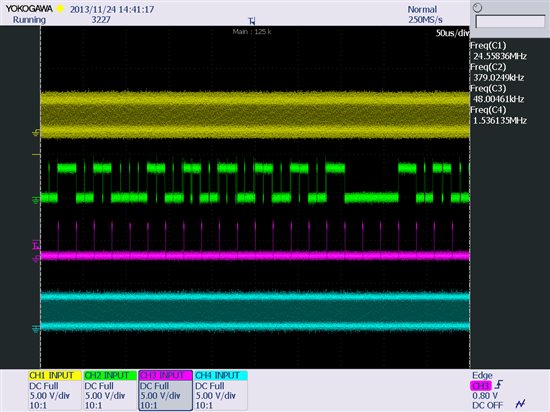
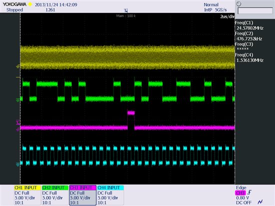
    If the beep works but the DACs don't play back audio from the I2S interface, please check the I2S interface settings and the I2S signals on your board with a scope (attach a screenshot showing all I2S signals).

  • Here are a couple of screen shots showing the signalling on the audio interface between the AM1808 and the TLV320AIC3100 while playing a wave file using aplay. 

    Channel 1 (Yellow) MCLK set to 24.576MHz

    Channel 2 (Green) DIN

    Channel 3 (Pink) WCLK or FrameSync 48kHz

    Channel 4 (Turquoise) BCLK 1.536MHz

  • Im developing a new platform which includes am3352 and tlv320aic3100 codec, Im using linux-3.2.0-psp04.06.00.11. The kernel has ALSA which has tlv320aic23.c  tlv320aic26.c  tlv320aic32x4.c  tlv320aic3x.c  tlv320dac33.c drivers. Im wondering if my tlv320aic3100 codec fully compatible one of them and what I have to do to port my codec?

    Thank you

  • hello

    I implemented all mfd drivers and codec drivers of tlv320aic31xx to my platform but I cant aplay wav file via aplay, all the drivers probed without errors and aplay gives no error. But My codec doesnt generate any clock (codec is master). I dont know what the problem is, any advice?

    Thank you

    Emre

  • Hi ryan,

    may I see your changes please?

    Thank you

  • Hi Ryan,

    i am also using same chip set but not getting any sound via HPL and HPR lines.

    Could you able to solve the issue, if yes can you kindly  share?.

    Can you say how to check beep in sound card?.


    Regards

    Punith

  • Hi Punith,

    My issue ended up being due to a bad connection on the PCB between the AM1808 and the codec. My register values were all fine. Attached are the kernel files I customized to meet my needs, hopefully they will be of assistance to you. Please remember these are specific to my hardware configuration.  I used Linux kernel version 2.6.37.

    customfiles.tar.gz
  •  

    Hi All,


    Finally i am able to do some improvement in my codec , now i am able to generate beep (exactly 2khz by programming beep registers) .but still i am not able to get any audio in HPL and HPR line.

    In my case codec is slave and cpu is master. here is my clock configuration

    MCLK=5.6448MHZ

    BCLK=1.411MHZ(for 16 bit ws)

    WCLK=44.1KHZ.

    I tested the data in from cpu to codec by playing the wav file which contains only 'A5' data. feels DataIN is ok.

    here i am attaching my logic analyser output and register dump of codec chip set.

    If anyone have idea  kindly suggest me.


    Regards

    Punith

    ti3100_registers.zip
  • HI Ryan,

    can you tell me how you point pcb is an issue. I am also facing same problem from long time. i am able to generate beep exactly 2KHZ beep.
    Regards         

    Punith

  • Hi Punith,

    The issue I ran into was actually due to a damaged resistor on the DIN data line between the MCU and codec. Up until the point in time where I figured out what was happening I had been probing the signal on the MCU side of the resistor. Once I probed on the codec side of the resistor I instantly noticed the signal was missing. 

    I think the best suggestion I could make, which is what had me backtrack to the point of checking the hardware, is to turn on the DIN-to-DOUT loopback (bit D5 of the Code Interface Control 2 Register). This will echo the data coming in on DIN back out on DOUT allowing you to verify data is being received by the codec. If you don't see the  signal on DOUT then you may have an issue getting the signal to DIN. If you do see the signal then I think chances are some registers aren't configured correctly.

    I hope that helps!

    -Ryan

  •  Hi Ryan,

    Thanks for your reply. Here is some update :

    I did loop back from DIN to DOUT but not getting any signals in DOUT.
    and also i observed with loop back DIN amptitude is decreased and has some distortion.
    but without loop back DIN is ok.

    Did you say is it beacuse of pcb issue. but i am geeting beep with exactly 2KHZ and
    i programmed beep values for 2KHZ for fs=44.1k .


    and here is my cpu configuration for i2s. Kinldy chek my codec register and cpu configuration
    and if any differnce find out let me know.

    i2s_master            = 1   / cpu as master
    i2s_select              = 1
    audio_format            = 1   / i2s
    signal_inversion        = 1
    over_sample_rate        = 256
    sample_resolution   = 16
    word_select_size        = 16
    //pcm_sync_period         = 128
    msb_lsb_first       = 0     / msb is first
    sign_extend             = 0
    slot_index                  = 0
    slot_width                  = 16
    frame_width             = 1
    tx_data_mode            = 0
    rx_data_mode            = 0
    i2s_mclk            = port:PB05<2><1><default><default>
    i2s_bclk            = port:PB06<2><1><default><default>
    i2s_lrclk           = port:PB07<2><1><default><default>
    i2s_dout0           = port:PB08<2><1><default><default>
    i2s_dout1           =
    i2s_dout2           =
    i2s_dout3           =
    i2s_din             = port:PB12<2><1><default><default>


    Regards
    Punith