This thread has been locked.

If you have a related question, please click the "Ask a related question" button in the top right corner. The newly created question will be automatically linked to this question.

PCM4220 data format

Other Parts Discussed in Thread: PCM4220, TMS320C6745

Hi.

I am reading data from PCM4220 through  TMS320C6745.

I have the next configuration:

1) PCM4220

- Master mode

- Double Speed mode

- Classic filter response

- SUB0 = 0 and SUB1 = 0: Sub-frame 0

- OWL0 = 0 and OWL1 = 0: 24-bits

- FMT0 = 1 and FMT1 = 0: I2S

Audio serial port bit clock - 6,14407 MHz

Audio serial port left/right word clock - 96 KHz

Master clock - 12,2881 MHz

2) DSP

Codec connected through McASP.

Master clock - 24,576 MHz (Is it correctly ?)

My problem:

1) I connect  VINL-, VINL+,VINR-, VINR+ pin to the ground.

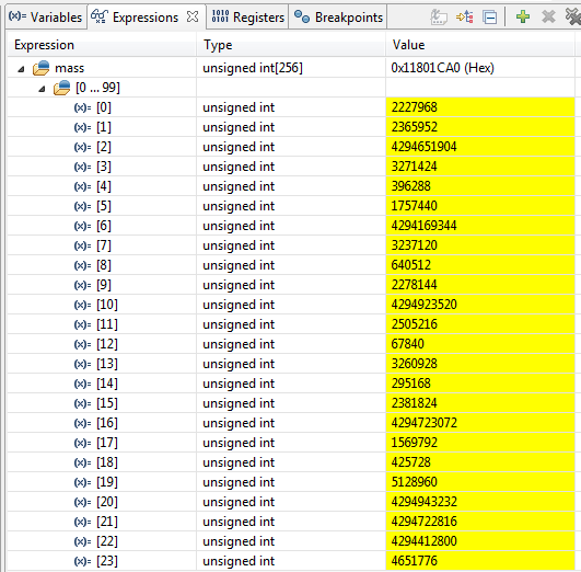
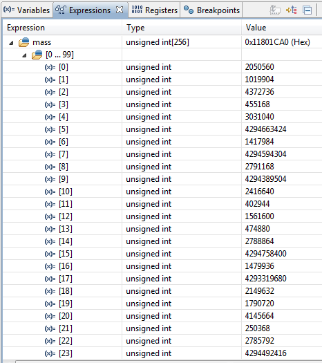
But my received DATA in the buffer are the next:

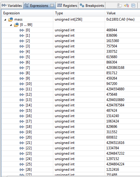
I don't understand why values do not match:

866304 and 4293863168

4293863168  and 851712

851712  and  459264 

etc.

Values should strive to zero, but I have values 4293863168. Why?

 Your help will save me a lot of time. 

Thanks.

  • Hi Alex,

    The McASP port should be getting the same master clock as the PCM4230 is, along with LRCK and BCK from the PCM4220, since it is in master mode. Try this and see if the output looks better.

    Justin
  • Hi Justin,

    I make two experiments:

    1) McASP master clock 24,576 MHz (VINL-    =  VINL+  = 1,96V)   and  (VINR-    =  VINR+  = 1,96V)

    2) McASP master clock 12,2881 MHz (VINL-    =  VINL+  = 1,96V)   and  (VINR-    =  VINR+  = 1,96V)

  • Hi Alex,

    The same clock signal must be used as the Master clock source for both the PCM4220 and the McASP. You cannot use separate master clocks for each, even if they are the same frequency. They must be synchronous.

    Justin
  • Ok, thank you Justin.

    I suggest my problem (e2e.ti.com/.../429136) .
    On my board Right channel high-pass filter and Left channel high-pass filter - was enabled. I connect DC voltage to VINL and VINR of the Audio Codec but high-pass filter BW = 22Hz to 40kHz.


    I slit paths on the circuit board and pull up (HPFDR & HPFDL) pin. Master clock I connect to 12,288 MHz - > my device work fine.

    But I have some questions.
    When I using Buffer Circuit with Standard Op Amps I have next:

    Buffer input (2,432V DC)
    Buffer output + (2,2085V DC)
    Buffer output - (1,7056V DC)

    ADC code after conversion:
    1011110000100011000000000000 bin

    after discard the least 8 significant bits:
    10111100001000110000 bin = 770608 dec

    I am using the next formula:

    U_input = (5,6 V x 770608)/ 16777216 = 0,257 V

    If
    2,2085V - 1,95V = 0,2585 V
    1,95V - 1,7056V = 0,2444 V

    My calculation is correct ?
  • Hi Alex,

    Are you following the example input circuits in the data sheet or the EVM? Do you have a AC coupling cap at the intput then biasing the input with the bias signal from the PCM42220?

    Justin
  • Hi Justin,

    I don't   have a AC coupling cap at the input.

    I have the next input part:

  • Hi Alex,

    It seems you are trying to input a DC signal and get a zero value correct? Then yes disabling the HP filters will be necessary along with no DC blocking caps. Keep in mind this part is designed for Audio so we do not test or design for DC accuracy and that you will have to determine if your observed accuracy is acceptable. It does seem that your calculations are correct.

    Justin

  • Hi Justin,

    Thanks for your answer.
    I don't see Verify Answer button.
    Thanks.