This thread has been locked.

If you have a related question, please click the "Ask a related question" button in the top right corner. The newly created question will be automatically linked to this question.

TPA 3123 high shutdown current

Other Parts Discussed in Thread: TPA3123D2

Hello;

I`m starting to do builds with many of your classD amplifiers (tpa -tas)

But for TDA3123D i had encountered a big issue;

In shut down mode (SD to low) the chip is consuming very much:

VCC-12v - 80mA in shut down

VCC-20V - 100mA in shut down

VCC-28V - 120mA in shut down

in idle with no input signal nonmuted the chip is consuming between 20-50mA

Mute pin is hardwire to low (always unmuted); sd pin is upped to vcc with 100kR

I have done 3 build until now and all of them have the bug.

Other build of my own (tpa 3106) don`t have this problem.

This is pretty fail in my book.
  • Anyone have the evaluation board for this chip to run some simple tests?

  • Hi, Mihai
    I have checked with TPA3123D2's EVM board, the shutdown current is lower than 1mA, and the quiescent supply current with out shutdown (PVCC=16V)is 22mA. Maybe there has some issue in your board.
  • OK; i solved the enigma!

    In my pcb the gain is hardwire to max (36db)

    that means i have 9kR input impendance> and because of that; i used 10uF input caps - for having linear response down to 20HZ (cut is on 2HZ - -3db)

    Now, because o have used 10uF on input cap; i also used 10uF on bypass ; according to datasheet (the start up rate to avoid pop-up)

    Now: from my measurements, when i power up the tpa (sd high -  normal operation) for some seconds ; amp is mute but the supply current is ~ 100mA !; after the start of tpa (normal operation) the supply current is back to 20mA. Now, if i i put sd low (shut down) the tpa will shut down but for 7 seconds supply current is again100mA!; and after 7 seconds supply current will drop indeed to 1 mA. this test was done with 16V.

    For 28V VCC the shut down high current consume(100mA)  will last 14 seconds ; and after that will drop below 1mA .... 

    SO; for large bypass capacitor ; the startup-shutdown current will be big (~100mA) for some several seconds;

    I need a designer engineer to explain me what part from TPA will consume this much on startup-shutdown (the time when bypass capacitor is charged-discharged; My guess is that the supply reference circuit will drain this much current in  chargeup-discharge sequence with some internal resitors but i need to be sure that long time shut down current (14 seconds with 100mA for 28V supply will not destroy some internal regulators...)

  • Hi, Mihai
    Glad to hear you that you have solved the enigma! But I think your board still has some issues which I think not make sense. Can you share your schematic and I will review it later.
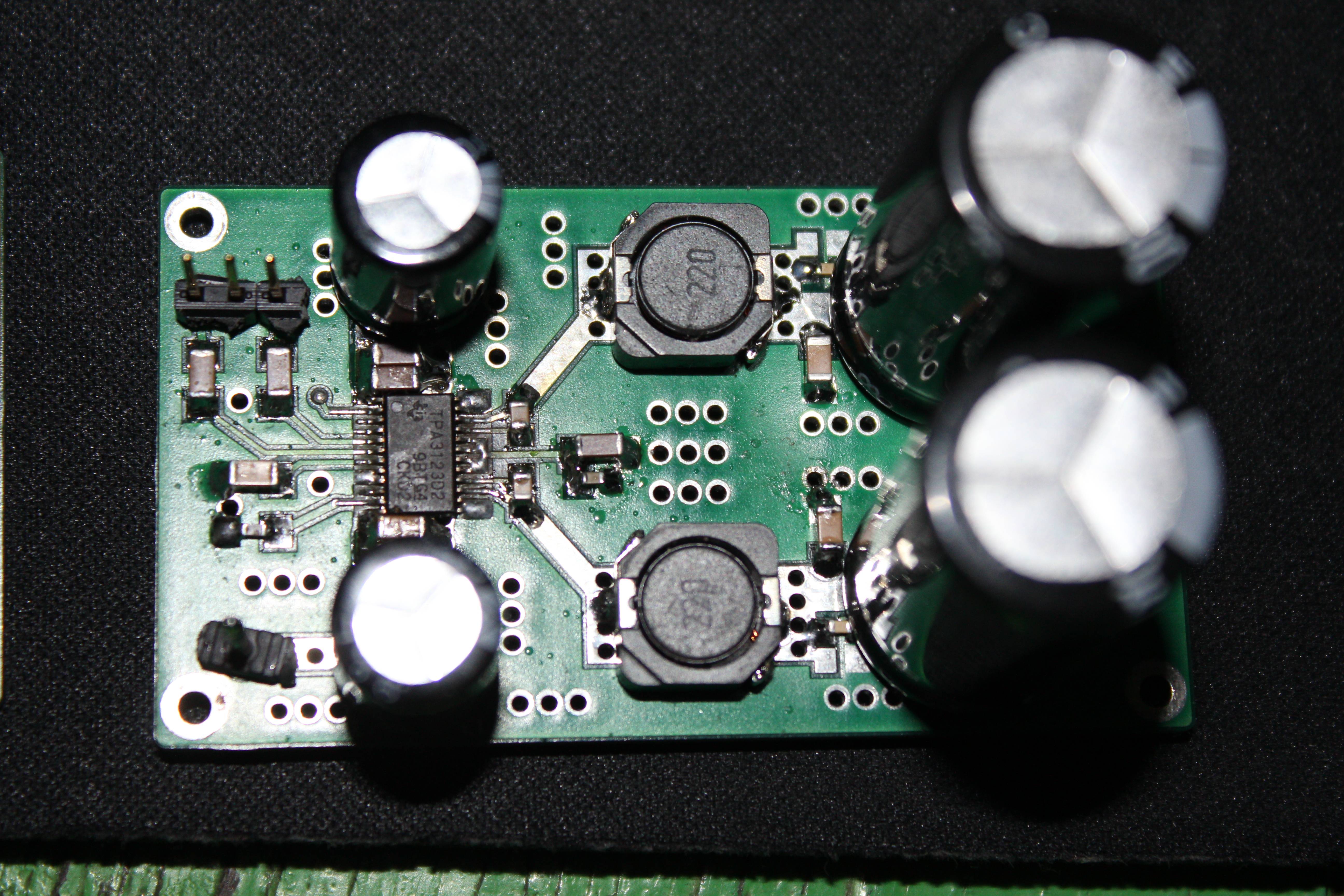
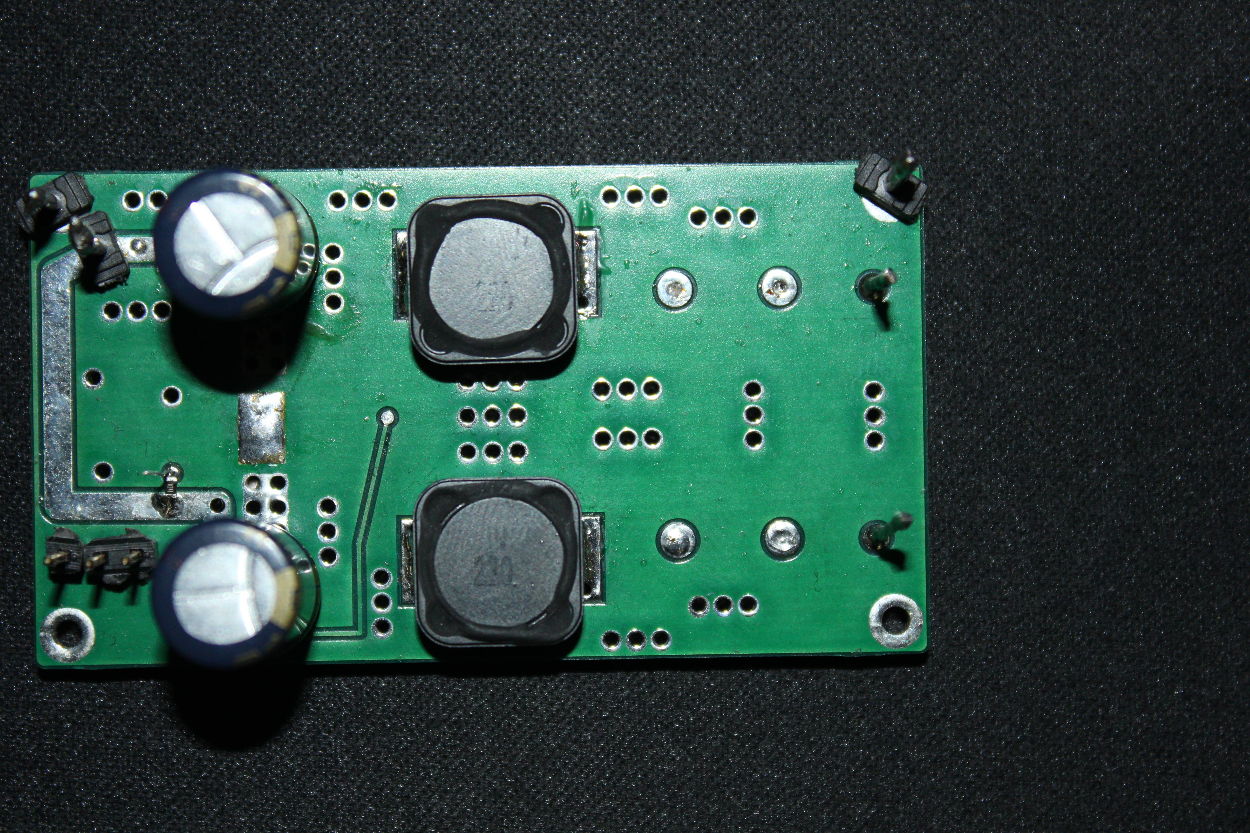
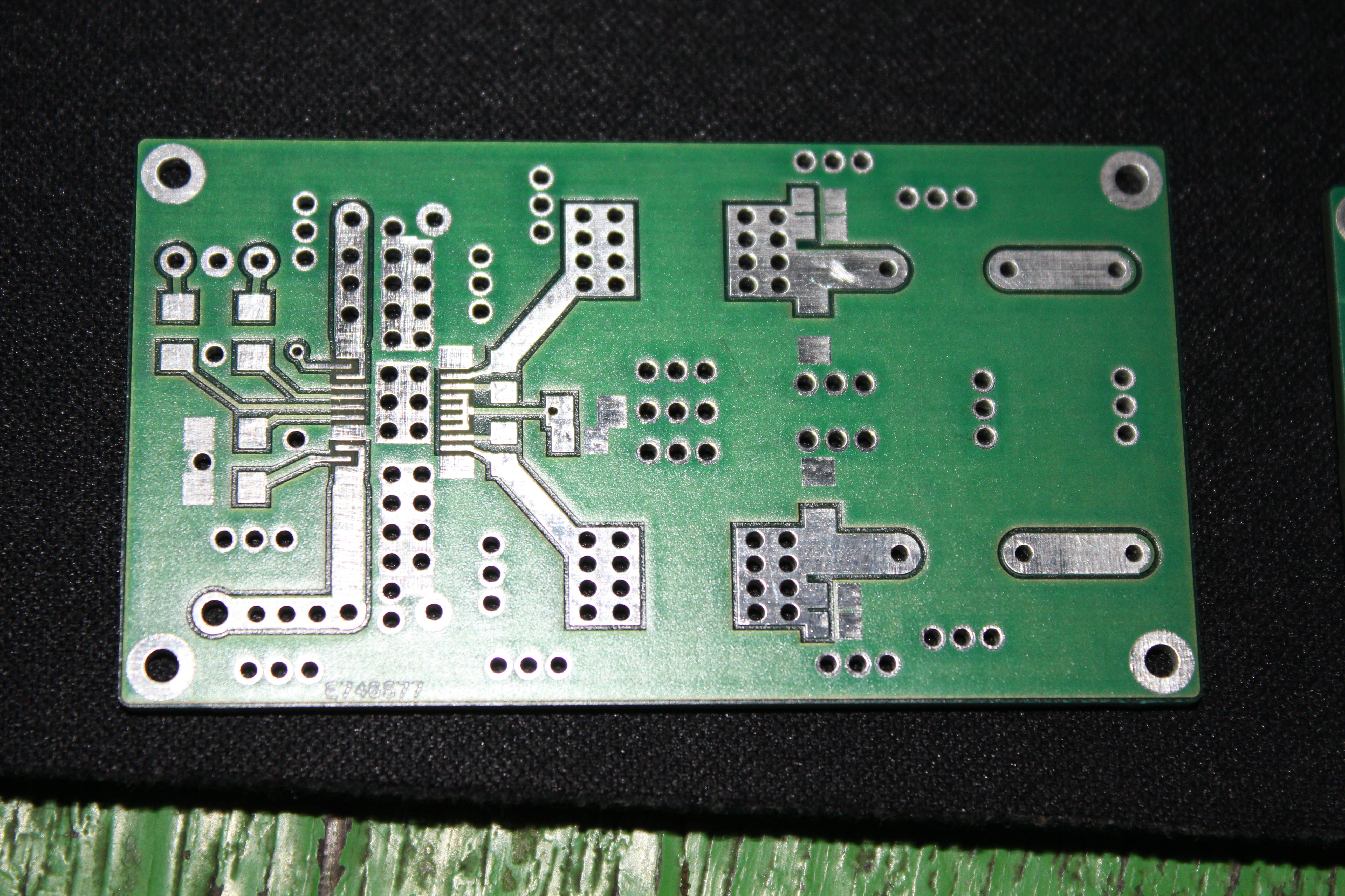
  • The board as you see in first picture is very simple and basic; and nothing can go wrong with that... after all the amp is working fine; except the shutdown issue.

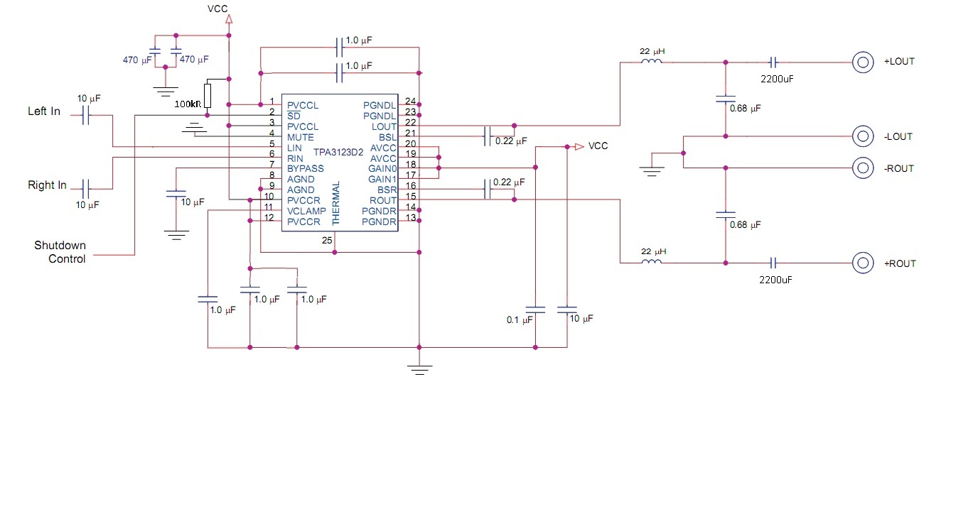
    The schematic is basically identical to datasheet; except gain control pins and the mute pine are hardwire; to vcc and gnd;

    Can you replace the bypass capacitor on evm board with 10uF or greater? and then do same tests?

  • HI, Mihai

          Yes, it make sense. The BYPASS is the reference for pre-amplifier input. Also controls star-up time via external capacitor. If you increase the capacitor, internal circuit of TPA3125D will guarantee the reference voltage until it increase to a proper level as the datasheet says. You can find that at the beginning of the start up, the PWM duty cycle is not 50% (normal state should be 50%), it is because the reference voltage of pre-amplifier is still lower than normal. Suggest you  use 1uF as the BYPASS pin capacitor.

         TPA3123 start & shutdown.pptx

  • Hi, Mihai

        You can find the attachment which I send in the former post.

  • ok now; this is normal behavior;

    i have already start to decrease the bypass capacitor to the point of avoiding  the pop up as much as possible due to high input caps; and i don`t want to redesign the pcb because already made 50 of them.

    thank you for the last tests :D ; and clarifying  the issue;

    Anyway, maybe you should suggest to the team to make a new revision for the datasheet in where the bypass section to be more explicative like this thread :) 

    Moving now to other builds (i have a plenty of them)

  • Hi, Mihai
    Thank your for your interesting for so many TI audio device and thanks for your suggestion about the datasheet, it is very meaningful.