This thread has been locked.

If you have a related question, please click the "Ask a related question" button in the top right corner. The newly created question will be automatically linked to this question.

PCM1863 differential input configuration

Other Parts Discussed in Thread: PCM1863

The customer want to configure the PCM1863 as differential input (VIN2P, VIN2M). The schematic is shown as below,

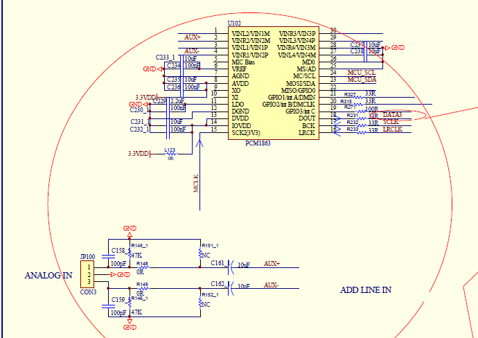
Case 1: When they add signal on pin 1 & 2 of ANALOGIN, the loudspeaker makes a sound.

Case 2: When they add signal on pin 3 & 2 of ANALOGIN, the loudspeaker makes no sound. I have observed that there were signals added on pin VIN2M.

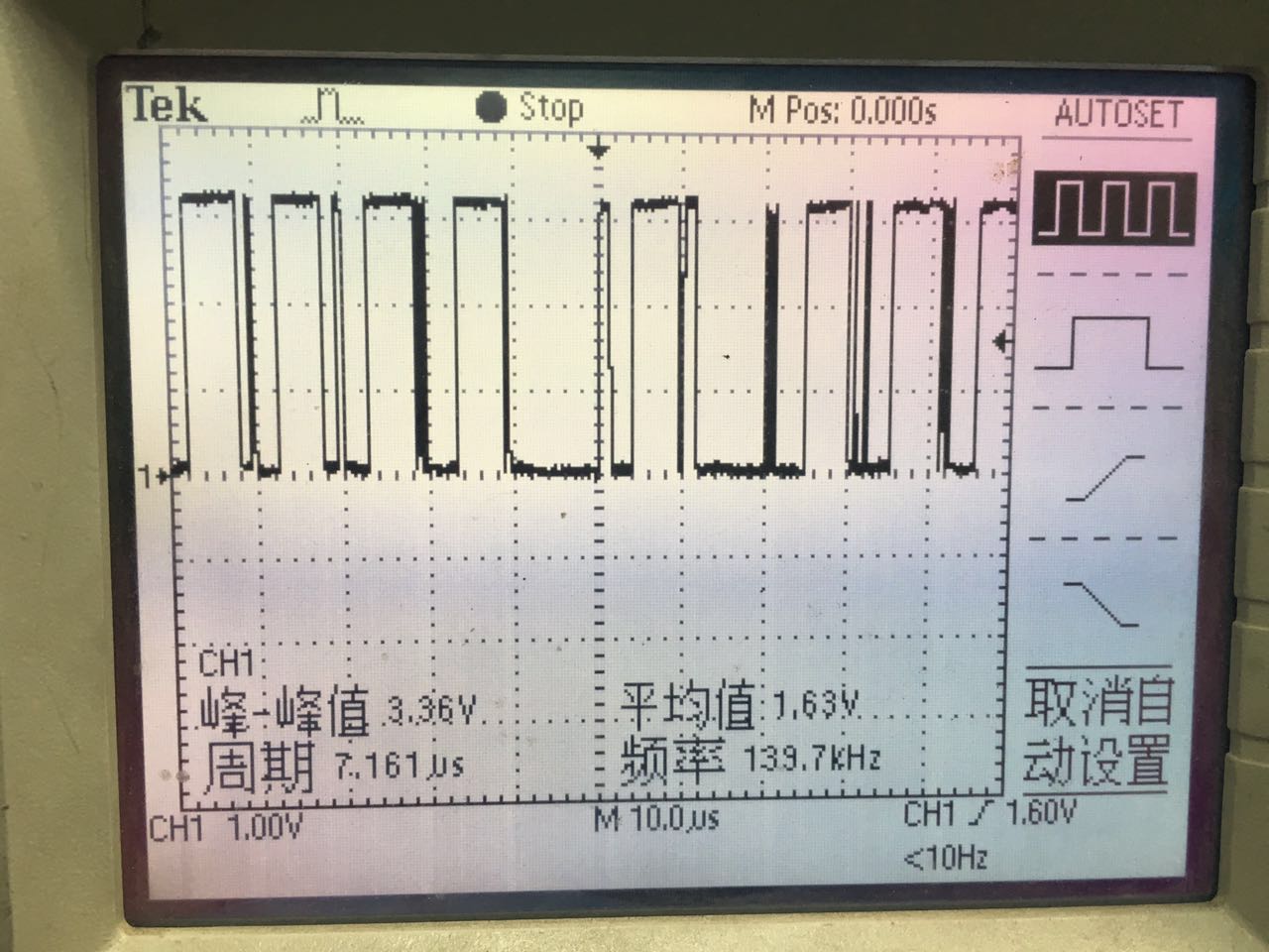
The the waveform of DOUT pin for case 2 is shown as below:

And the configuration of the register is indicated as below:

    Pcm1863_Write_Byte(0x07, 0x10);

    //Pcm1863_Write_Byte(0x09, 0x10);

    Pcm1863_Write_Byte(0x1, 0x0c);

    Pcm1863_Write_Byte(0x2, 0x0c);


    Pcm1863_Write_Byte(0x20,0x11);

    Pcm1863_Write_Byte(0x26,0x3);

    Pcm1863_Write_Byte(0x27,0x3f);

So do we need to do other configuration on the register? Or this issue is caused by other problems? 

  • Hi Robin,

    I used your register settings on the EVM, and it seems to work, is the speaker playing the audio from the right channel or the left channel? It seems in the schematic that the + and - signals are reversed for the input into the ADC, but this should stop audio from being captured.

    For the 0x1 and 0x2 register writes, am I correct in assuming you meant 0x01 and 0x02 for the register address?

    Justin
  • Hi Justin,

    So if I want to configure it as differential input, I just need configure 0x07 resgister?

    1. I have asked the customer about right channel or left channel, but still not get the answer. Do you think it matters?
    2."but this should stop audio from being captured" should be "should not stop"?
    3. 0x1 and 0x2 register means 0x01 and 0x02 for the register address.

    And I'm sorry for make a mistake, the phenomenon should be:

    Case 1: When they add signal on pin 3 & 2 of ANALOGIN, the loudspeaker makes a sound.
    Case 2: When they add signal on pin 1 & 2 of ANALOGIN, the loudspeaker makes no sound.

    Do you have any suggestion to debug it?

    Thank you.

    Robin
  • Hi Robin,

    The registers 0x06 and 0x07 select which input pins will go to the two ADCs in the part. Am I correct in stating that AUX+ and AUX- go into pins 2 and 4 in the schematic above? this means that setting register 0x07 to value 0x50 (keeping the reserve bit high) will set the input to the Right ADC as the differential pair of VIN2M and VIN2P. From this you should see data on the right channel in the I2S data. If your amplifier is set up to play the right channel audio you should then hear it on the output. If your amplifier is set up to play audio on the left channel and you don't have the PCM1863 MUX settings correct, you will be getting VINR1 audio output from AUX-.

    To verify this, get a capture of the data line with the LRCK, and check what channel data you see when you change settings/inputs.

    Justin