A related question is a question created from another question. When the related question is created, it will be automatically linked to the original question.
If you have a related question, please click the "Ask a related question" button in the top right corner. The newly created question will be automatically linked to this question.
Welcome to E2E, Thanks for your interest in our products!.
I am afraid we don't have any driver available for this device, this is a simple part which configuration only requires the write of a couple registers.
i Have gone through the registers, specifically the Register 3 talks about configure the Chip 16-bit MSB-first left-justified, 20-bit MSB-first left-justified, 20-bit MSB-first left-justified and 20-bit MSB-first I2S mode,
can you please help us understand the difference between these modes and 20-bit MSB-first I2S mode means are the left justified modes different than the I2S mode?
secondly the three wire MC,MD,ML interface don't follow any specific protocol, do we need to bit bang them to config the chip for I2S mode?
Third if yes is there any sample source code for the bit bang with TI?
The different formats supported by this device are highlighted in the datasheet, page 20 and 21. The difference between left-justified and I²S mode basically is the reverse polarity of right and left channels respect the word clock high or low value and the 1-bit offset present when the data starts on the I²S format.
This is a quite old device, which employees a three-wire serial interface for the software control. The 15-bit word that is written to the device has the information about the register used and the device programming, please refer to page 27 for the register write format.
Unfortunately we don't have a tool capable of interfacing with this device to program it.
I have created a quick register configuration to set the device in I²S mode so you can use it as an example of the device configuration.
From the information you shared, it seems the issue is related to a clock error, this device expects to have 32, 48, or 64 bit clocks in one word clock, otherwise the clocks will be considered as invalid. In your application, BCLK has a frequency of about 58×Fs, which is not supported by the PCM3003. Also, system clock is running at 275×Fs, which is not supported, only 256×Fs, 384×Fs and 512×Fs, frequencies are supported.
Below are the settings, we are using in Program registers of PCM3002:
Register0: 0x01FF
Register1: 0x03FF
Register2: 0x0442
Register3:0x060C
We are setting up I2S mode format on audio codec. Program registers are being set through bit banging using memory modification tools on connected GPIO's (ML, MC and MD).
Below are the clock settings:
sampling frequency (fs) is 48 KHZ
bit clock is set to 3.072 MHZ (20-bit MSB first I2S format for 2 channels) <= 32*2*fs
System clock is set to 24.57 MHZ <= 512 *fs
We are getting noise output on Vout pin when audio file is played with above settings.
Below are my questions:
1. Do we have any verification tool to check if program registers are set properly or not?
2. If program registers are set properly (Assuming), what should be the output on Dout and Vout pins?
Thanks for the feedback. The Clock settings seems fine now, however, I would like to recommend checking the format used by the host processor and codec. I have seen cases where a formar mismatch leads into noise on the analog and digital outputs.
Unfortunately, there is no verification tool available, as mentioned before this is a quite old device which tools and support options are limited. Assuming the registers are properly set, the digital output (Dout) should stream the content recorded on the ADC inputs, having a toggling on the lower bits (noise floor), while the analog output (Vout) should stream the audio provided through the digital input (DIN).
Do you have some captures of both Dout and Vout with and without providing analog and digital inputs?.
Thanks for the additional feedback, the steps from the document you shared seems fine for me. The output audio seems definitively strange, I suspect there is a problem between the device expected format and processor's data format. One thing I would like to recommend in order to move forward and discard a problem with the device is to try using another digital Audio master, if the issue is still there, it is likely that the PCM3002 is not being properly configured. Unfortunately there is not much information abut this part and the way to program it is not very flexible.
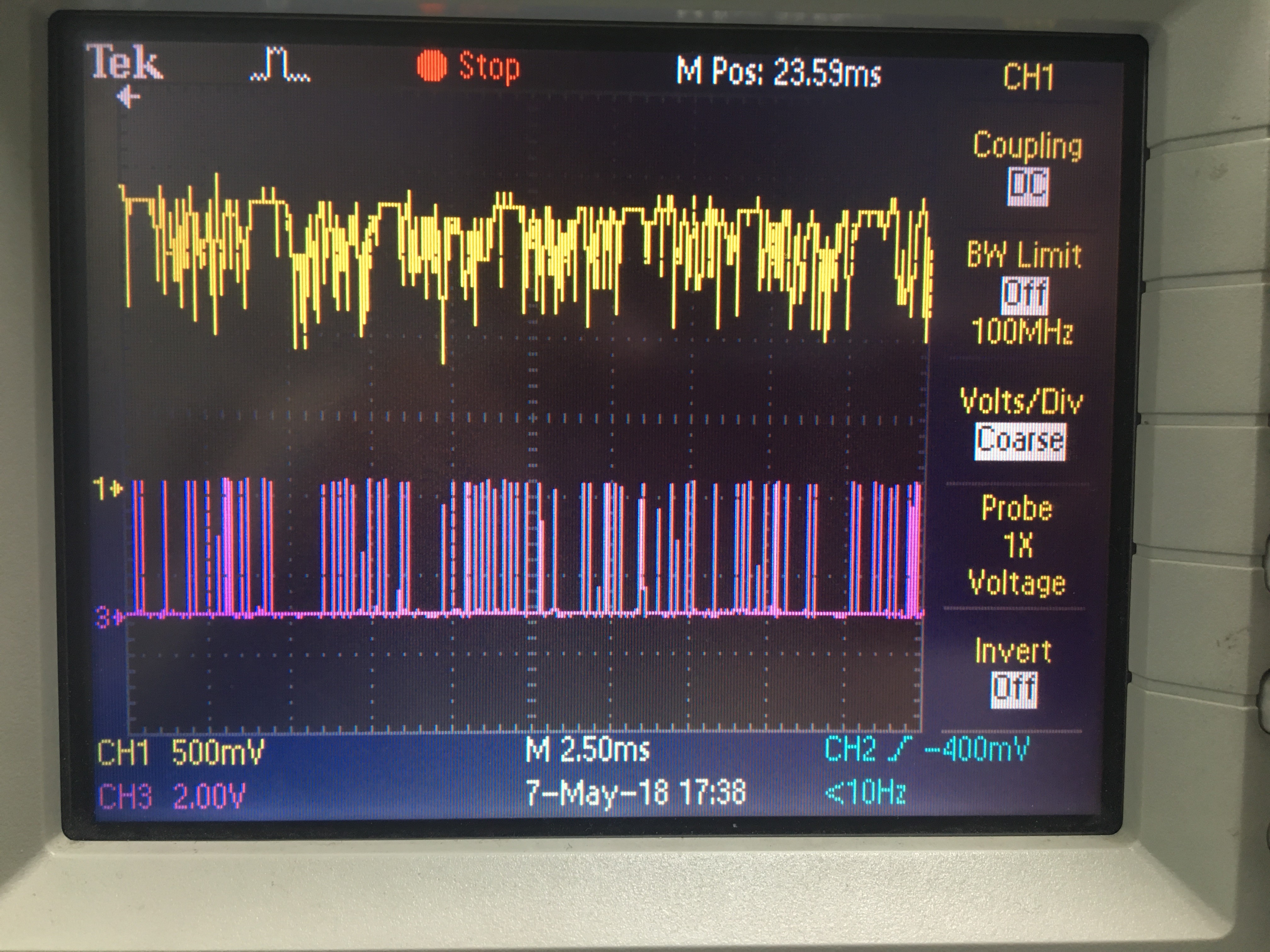
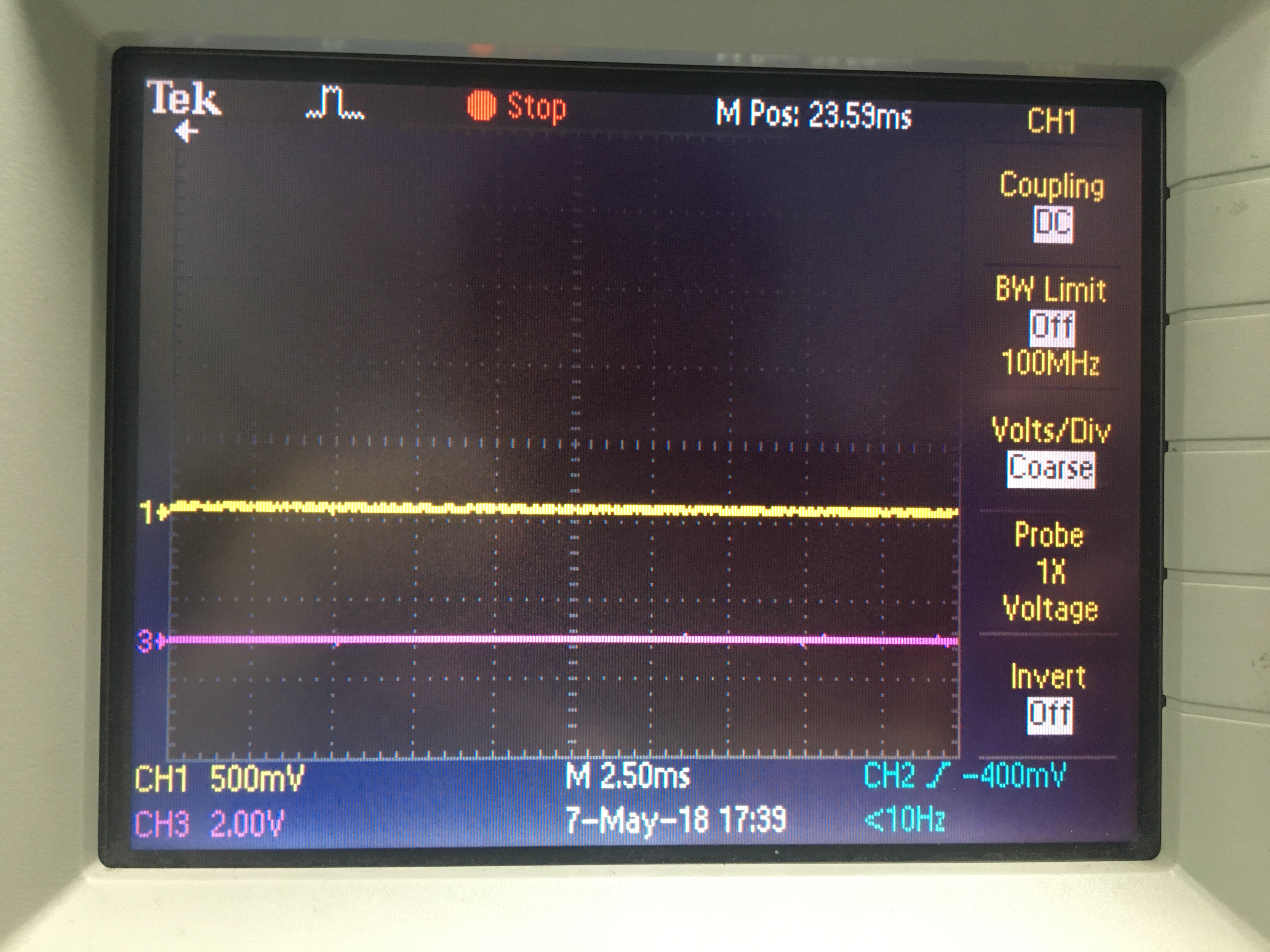
Referring to last waveform shared about Vout and Dout, there has been mistake while tagging those waveform.
Yellow colored waveform indicates Vout output and pink one represents Dout output.
Unfortunately, we do not have another digital audio master to test on. Most probably, program register settings done through bit banging seems to create some issues. As with reset and after setting up program registers, we are getting same results on output pins. Plus, even after enabling Mute, we are receiving output at both the pins Vout and Dout. Document (shared in last reply) provides details about timing diagram while setting up program registers. Please confirm if the actual time frames are in valid ranges or not.
After looking at the control interface clock specs,it seems the signals used to configure the part are faster than the expected from the device. I am not sure if this could be an issue, there is not much information about this type of interface, so the only recommendation I can provide is to try changing the configuration signals to make them slower and meet the timing details from the datasheet. The I²S clocks seems fine, but my only question would be to verify if effectively the data starts one bit after the LRCK changes (as should be on I²S format). One other suggestion I have is to set the host processor to operate in left justified mode and operate the PCM3003 in default mode without any configuration.