This thread has been locked.

If you have a related question, please click the "Ask a related question" button in the top right corner. The newly created question will be automatically linked to this question.

TPA3132D2: Audio Input capacitance question

Part Number: TPA3132D2

Hi Sirs,

Sorry to bother you.

As another discussed, 


We have confused that why change series capacitance value the Voltage amplitude will be change too?
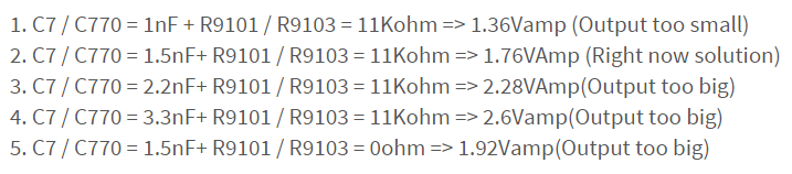
Could you help to explain it?

Thanks!!


  • Hi ShuCheng,
    The input capacitors and the input/external resistors forms a HPF. Please find more explanation in the section 7.3.2 in the datasheet. Very low input capacitors caused very high HPF bandwidth, and nF level is quite low. I think that is why the output amplitude increases with the the input capacitance increases. The resistor divider can scale the input amplitude down, so setting R9101 to 0ohm increases the output amplitude.
    As I recommended before, resistor divider is not a good way to shrink the input singal. The best way is to lower the output signal amplitude from DAC/Codec.
    Best regards,
    Shawn Zheng
  • Hi Sirs,

    Thanks for your reply

    Update our question as below

    Q1. AMP front-end resistor divider problem: If you consider the resistance tolerance, I think there is doubt in this argument. The Audio codec itself is also a small amp output, and this amp also has a tolerance.
    Q2.  Is the output amplitude adjusted by the AMP front-end series capacitor and resistor? Is there a formula conversion? Ex: codec output 8/8ohm speaker.
    Q3. As Q2. According to the spec setting gain value, with input cap., amp internally generates input impedance corresponding to HPF value according to external settings.Now TI recommends that the front-end series resistance conflicts with the internal input impedance? The following Spec seems to have no reference value.

    Q4. According to the above TI recommendation, the output amplitude is adjusted by the front-end resistor and capacitor to achieve the end user speaker module specification. The relative HPF value also has the opportunity to filter out the required frequency of the end user. The two seem to be in conflict.

  • Hi Shucheng,
    TI always recommend users NOT to use complex circuit(e.g. extra buffer, resistors...) on the AMP input. Again and again, the best solution is to lower the input signal amplitude in this appication. The resistor divider circuit could resolve the input signal amplitude issue, but introduce the other issues(e.g pop noise, lower frequency loss...). We can explain your questions, but I don't think the resistance tolerance is related to your question.
    If you use high value input capacitors, the pop noise performance could be very bad. While if you use very low value input capacitors, the pop noise performance can be improved, but too high HPF bandwidth could filter some of the lower frequency components. You can try to do tuning to find an appropriate value capacitor to balance this considering that I was told that the input resistor divider ciruit is the only possible solution, but keep in mind that the best solution is always to shrink the input signal amplitude and use 1uF input capacitors, which makes the best pop noise performance and frequency response performance.
    Best regards,
    Shawn Zheng