This thread has been locked.

If you have a related question, please click the "Ask a related question" button in the top right corner. The newly created question will be automatically linked to this question.

OPA1632: Complete differential amplifier opa1632, the output waveform peak-to-peak difference is large, how to solve

Part Number: OPA1632

Hello, we use opa1632 single-ended to differential, the two outputs (non-inverting output, inverting output) peak and peak are not equal [according to the data sheet, we believe that the output should be 180° phase difference, peak-to-peak waveform, if not, Thank you for correcting me! ! 】 In the case where the input peak-to-peak value is 2V, the difference between the two ends is from 20mV to 120mV. What may be caused by this? How to verify and modify

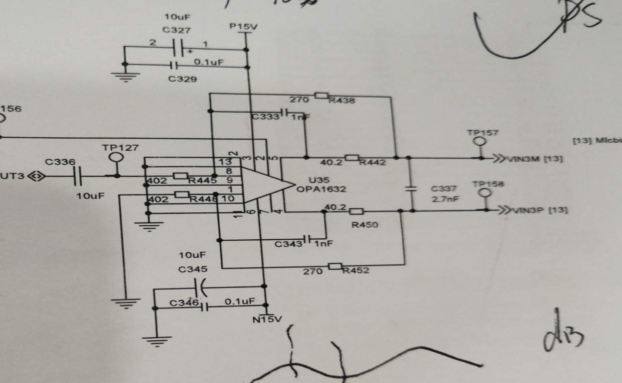
The following is the circuit diagram

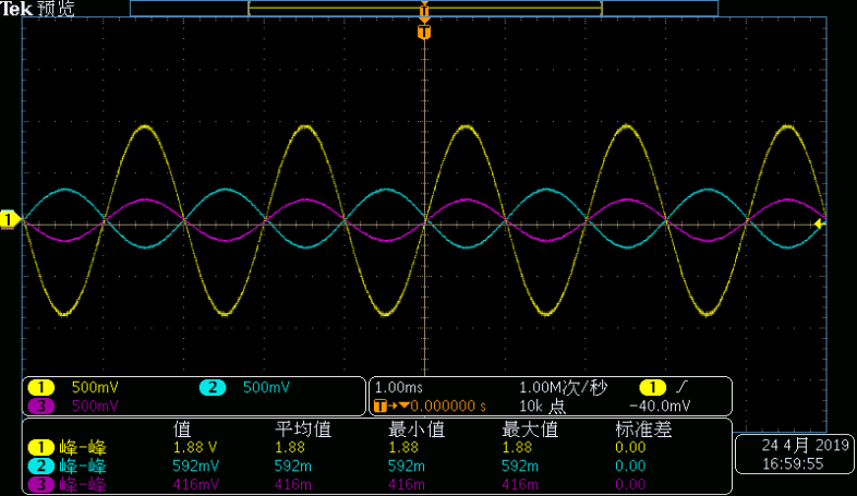
Signal detection when the input is peak-to-peak 2V, frequency is 500Hz, and offset is zero
Yellow waveform is the input signal
Blue waveform is the inverting output
Purple waveform is the non-inverting output

  • Hi user6034314,

    The input impedance on both sides must be equal, otherwise it will effect the gain, just like an inverting amplifier. What is the source impedance on the other side of the coupling capacitor? Can you put a 10uF capacitor and that impedance in series with ground on the reference input side also?

    Best regards,

    Sean

  • Hi Sean,

    1. Do you mean that the input impedances of the non-inverting input and the inverting input need to be equal?
    2, I hope that you can point out on the map which is the other side of the coupling capacitor, I am afraid that I will not be able to reach you.

    3. Why should I place the capacitor and impedance at the reference input? Avoid clutter interference?

    Best regard!

    Zhang

  • Hi Zhang, 

    Sean is asking for the impedance that is connected to UT3 before capacitor C336. 

    Regards,