This thread has been locked.
If you have a related question, please click the "Ask a related question" button in the top right corner. The newly created question will be automatically linked to this question.
Hi,
We are using the TPA3251 and TPA3255 in our commercial class D power amplifier product range.
Our design team place a strong emphasis on ensuring that our end users connected speakers are protected under all possible failures modes of the TPA chip.
We currently have a DC detection circuit that feeds into a protection relay that can remove the speaker from the circuit if a significant amount of DC is detected on the line.
We would like to consider removing the DC protection circuit and relay as it adds significant cost to our BOM.
On Page 19 of the TPA3255 datasheet it states the following:
"9.4.1.3 DC Speaker Protection
The output DC protection scheme protects a speaker from excess DC current in case one terminal of the
speaker is connected to the amplifier while the other is accidentally shorted to the chassis ground. Such a short
circuit results in a DC voltage of PVDD/2 across the speaker, which potentially can result in destructive current
levels. The output DC protection detects any unbalance of the output and input current of a BTL output, and in
the event of the unbalance exceeding a programmed threshold, the overload counter increments until its
maximum value and the affected output channel is shut down. DC Speaker Protection is disabled in SE mode
operation."
My questions are:
1) Is the above statement where a speaker wire touches the chassis the only mode of failure that is protects a speaker against DC?
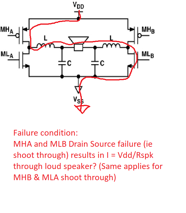
2) Is there any protection against the high side and low side full bridge simultaneous failure (ie Drain Source Short) that would allow a large amount of DC to go to the speakers?
Or is this event so unlikely/impossible to occur that it’s not feasible to protect against?
Kind Regards,
Jesse
Hi Jesse,
1. As stated on datasheet, "The output DC protection detects any unbalance of the output and input current of a BTL output". As long as there is current unbalance between on the bridge, the protection will be triggered. So at least short to GND or short to PVDD cases can be protected.
2. Do you mean the high side and low side switches on the same BTL leg? It's called "shoot through" and avoided by internal logic.
If you are talking about the high side and low side switches on different leg, the device won't do anything to protect according to the working principle description.
Thanks!
Regards,
Hao
Hi Jesse,
High side and low side FET on different legs turn on at the same time is different from shoot through case. It's normal working principle for class D amps.
DC protection detect any unbalance current between MHA and MLB, making sure there is no other path allows for the current. For the current limitation, it's another topic. Please refer to the "Overload and Short Circuit Current protection" on datasheet.
Thanks!
Regards,
Hao
Thanks Hao,
Understood that shoot through refers to a failure on the same leg and this is protected by the internal chip logic (as you said).
With a "High side and low side FET on different legs turn on at the same time" I understand that these turn on/off for the PWM modulation scheme of the amplifier during normal operation. However, I am worried about the case where they both turn on for (t = infinity) due to dual FET failure so the speaker would end up seeing DC. If this fault occurred, I really don't see how any DC protection to detect a current imbalance would able to turn the driving FETS on the H bridge off at this point because they are blown. It looks like the driving FETs connect directly to PVDD.and GND so there is no upstream switch for any protection circuit to shut these off.
I think i've answered my own question now. We will continue to use the relay to be 100% safe. Please let me know if you disagree as I am keen to remove the relay if I can be 100% sure the speaker is protected under all failure modes of the TPA chip.
Best regards,
Jesse