This thread has been locked.

If you have a related question, please click the "Ask a related question" button in the top right corner. The newly created question will be automatically linked to this question.

PCM1864: PCM1864 only outputs 16-Bit Audio Samples

Part Number: PCM1864
Other Parts Discussed in Thread: PCM1862, PCM1865, PCM1863

Hi,

PCM1864 is configured to run in 32-Bit TDM format (8 Slots, each 32-Bit wide = 256 Bclk ratio).

Register 11 is set to 0x13 so to output 32-Bit samples - this all works fine and I receive samples but only 16-Bit wide (then 16-Bit zeros, and then another 16-Bit sample from next ADC channel).

Do I have to do something special to get the full 24-Bit samples coming from the ADC ?

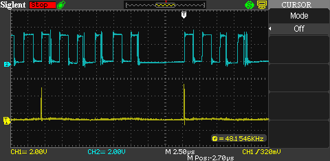
I checked timing with an osclloscope- looks all gut (48kHZ Framesync, 12.288MHz Master Clock and bit Clock).

Regards,

Sebastian

  • Hi Sebastian, 

    Not sure how you are determining this,  but when I configure register 11 to 0x13 I get 24 active bits and 8 pad bits.  Can you provide a scope capture of the WCLK, and DOUT, with a full-scale input on CH1, and no input on Ch2?

    best regards,

    -Steve Wilson

  • We are using a PCM1864 and a PCM1862 in TDM8 scheme and as you can see from first photo that we have 16 active bits and 16 zeroes for each slot - this is also what I see in the memory of our DSP. The lowest 16-Bit are always 0

  • Bitclock and MClock are both 12.288MHz

    Framesync is 48kHz

    Init code is:

    bool CPCM1864Drv::Init()
    {
      #if 1

        bool retVal = true;
        unsigned char Buf[2] = {0x00,0x80};

        Buf[0] = PCM186X_PAGE;
        Buf[1] = PCM186X_RESET ;
        retVal &= mpI2CDrv->WriteRead(mI2CAddr,Buf,sizeof(Buf),0,0);

        osDelay(10);

        Buf[0] = PCM186X_PAGE;
           Buf[1] = 0x00 ;
           retVal &= mpI2CDrv->WriteRead(mI2CAddr,Buf,sizeof(Buf),0,0);

         Buf[0] = 0x19;
           Buf[1] = 0xFF ;
           retVal &= mpI2CDrv->WriteRead(mI2CAddr,Buf,sizeof(Buf),0,0);


          Buf[0] = 0x01;
           Buf[1] = 0x50 ;
           retVal &= mpI2CDrv->WriteRead(mI2CAddr,Buf,sizeof(Buf),0,0);

             Buf[0] = 0x02;
           Buf[1] = 0x50 ;
           retVal &= mpI2CDrv->WriteRead(mI2CAddr,Buf,sizeof(Buf),0,0);

             Buf[0] = 0x03;
           Buf[1] = 0x50 ;
           retVal &= mpI2CDrv->WriteRead(mI2CAddr,Buf,sizeof(Buf),0,0);


             Buf[0] = 0x04;
           Buf[1] = 0x50 ;
           retVal &= mpI2CDrv->WriteRead(mI2CAddr,Buf,sizeof(Buf),0,0);


           //Assign inputs to ADCs

         Buf[0] = 0x06;
         Buf[1] = 0x50;
         retVal &= mpI2CDrv->WriteRead(mI2CAddr,Buf,sizeof(Buf),0,0);

         Buf[0] = 0x07;
         Buf[1] = 0x50;
         retVal &= mpI2CDrv->WriteRead(mI2CAddr,Buf,sizeof(Buf),0,0);

         Buf[0] = 0x08;
         Buf[1] = 0x60;
         retVal &= mpI2CDrv->WriteRead(mI2CAddr,Buf,sizeof(Buf),0,0);

         Buf[0] = 0x09;
         Buf[1] = 0x60;
         retVal &= mpI2CDrv->WriteRead(mI2CAddr,Buf,sizeof(Buf),0,0);


         if (mEnableTDM)
         {
          Buf[0] = 0x0B;
           Buf[1] = 0x13; //TDM;
           retVal &= mpI2CDrv->WriteRead(mI2CAddr,Buf,sizeof(Buf),0,0);


           Buf[0] = 0x0C;
           Buf[1] = 0x01; //4 Channel Output pnly ;
           retVal &= mpI2CDrv->WriteRead(mI2CAddr,Buf,sizeof(Buf),0,0);

              Buf[0] = 0x0D;
           Buf[1] = mTDMPos; //4 Channel Output pnly ;
           retVal &= mpI2CDrv->WriteRead(mI2CAddr,Buf,sizeof(Buf),0,0);
         }
         else
         {
           Buf[0] = 0x0B;
           Buf[1] = 0x00; //I2S;
           retVal &= mpI2CDrv->WriteRead(mI2CAddr,Buf,sizeof(Buf),0,0);


           Buf[0] = 0x0C;
           Buf[1] = 0x00; //2 Channel Output pnly;
           retVal &= mpI2CDrv->WriteRead(mI2CAddr,Buf,sizeof(Buf),0,0);
        }


           Buf[0] = 0x70;
           Buf[1] = 0xE1;
           retVal &= mpI2CDrv->WriteRead(mI2CAddr,Buf,sizeof(Buf),0,0);
           osDelay(20);


        Buf[0] = 0x20; //Slave Clock Audodetct
          Buf[1] = 0x2F;
          retVal &= mpI2CDrv->WriteRead(mI2CAddr,Buf,sizeof(Buf),0,0);


        Buf[0] = 0x70;
        Buf[1] = 0xE0;
        retVal &= mpI2CDrv->WriteRead(mI2CAddr,Buf,sizeof(Buf),0,0);
        osDelay(20);

    #endif

      /*  for (int i=0; i<=120; i++)
        {
           Buf[0] = i;
           retVal &= mpI2CDrv->WriteRead(mI2CAddr,&Buf[0],1,&Buf[1],1);
           printf("PCM1864: Reg: %d - Val: 0x%02X\r\n",Buf[0],Buf[1]);
        }*/

        return retVal;

    }

  • Hi Steve,

    any comment on the scope images I have sent ?

    Regards,

    Sebastian

  • Sebastian, 

    I've looped in the primary support engineer for this device to comment. 

    best regards,

    -Steve Wilson

  • Hi Sebastian,

    I spent some time verifying this behavior and I do in fact see the same thing on an EVM. I believe this is because the even part numbers in the PCM186x family only have an SNR of 103dB. This translates to an ENOB of ~17bits. While ENOB is not usually something discussed in the context of audio converters, it looks to me like the noise bits are actually masked for these devices, which is why you do not see them as active data bits.

    There was a similar question on e2e in the past that seems to confirm this: 

    PCM1860 not seeing 24-bit resolution. - Audio forum - Audio - TI E2E support forums

    e2e.ti.com
    Other Parts Discussed in Thread: PCM1860EVM , PCM1860 , PCM1861 I have designed a board with the PCM1860 to operate in Master Mode. For testing I have been looking

    If you want higher resolution, I would recommend moving to the PCM1863 and PCM1865, which have an SNR of 110dB.

    Best,

    Zak

  • Hi,

    this is still a problem then because we only  get 16-Bit which result in 96dB SNR ?!

    To achieve >103dB we would at least need 18-Bits (17-Bits is only 102dB).

    So this is a mistake in the datasheet, I assume...