I've a project with TAS3251
This thread has been locked.
If you have a related question, please click the "Ask a related question" button in the top right corner. The newly created question will be automatically linked to this question.
Hi,
For high power applications, ferrite beads are strongly NOT recommended for EMC concerns. Any background that you are not using inductors?
The chip gets hot because you are using 0.68uF cap combined with ferrite beads. 0.68uF is good for inductor but not for FBs. It will increase the switching loss of the device significantly. If you remove the 0.68uF caps, the device should not dissipate lots of power.
Regards,
Sam
Hi sam,
Hi,
For the schematic,
Could you measure the power consumption on PVDD rail in the status your heatsink got very hot? Please also check the output pins to see if it's switching and output power.
Thanks!
Regards,
Sam
Hi sam,
The noise problem was solved when I dropped the C8 and C15 on my design, but the temperature still hasn't improved.
PVDD is completely normal when I try sine wave (youtube) to evaluate the quality of the design.
Something seems wrong with my design, it seems.
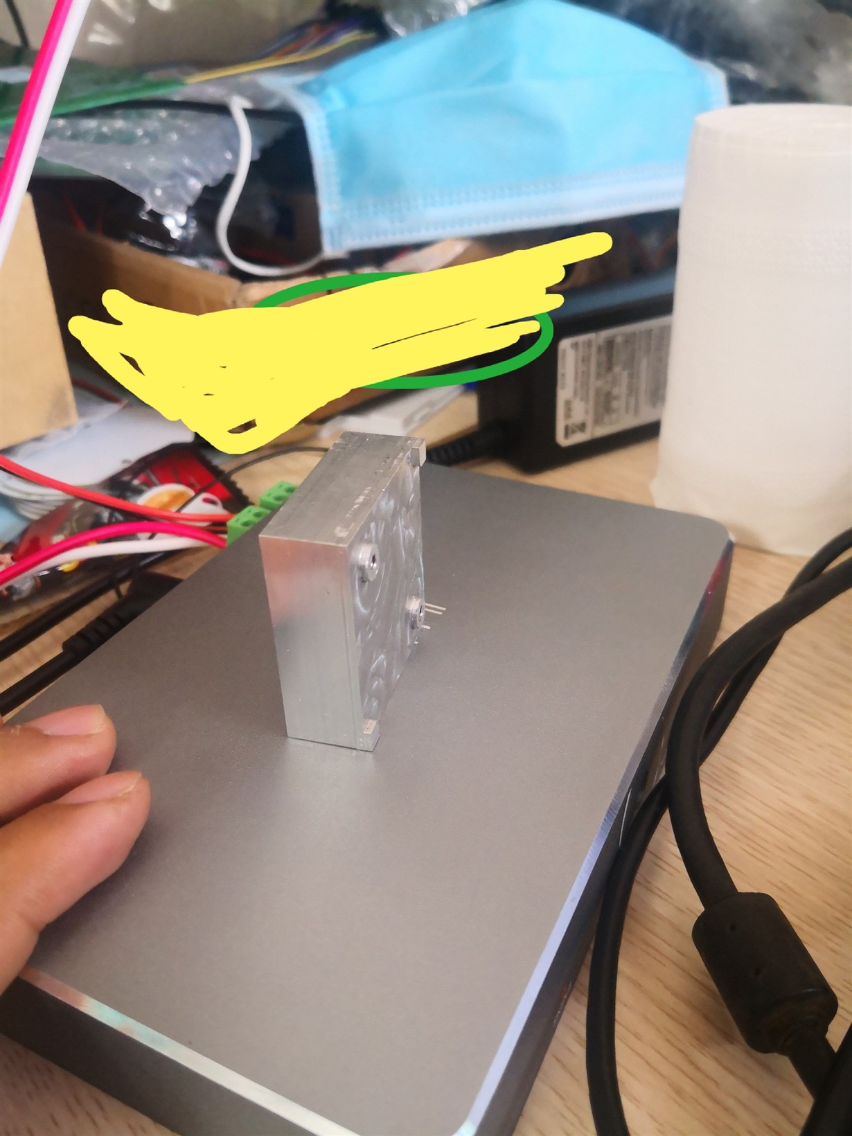
The heatsink is very hot even though the system only operates at 50W for both channels.
this is the heatsink for my design with the thermal aluminum case design will be led straight from the heatsink to the aluminum housing.
Regards,
KDS
Hi,
May I ask what loading you are using? Speaker resistance?
Is it possible for you to measure the input current and output voltage? So we can calculate the efficiency and compare with numbers on datasheet.
BTW, it's necessary to add MLCC decoupling caps on PVDD pins and they should be placed as close as possible to the pins. Or the inductive high voltage spike due to high di/dt at switching edges may kill the part.
Thanks!
Regards,
Sam