This thread has been locked.

If you have a related question, please click the "Ask a related question" button in the top right corner. The newly created question will be automatically linked to this question.

TLV320AIC3204EVM-K: external TLV320AIC3204 I2c control with EVM

Part Number: TLV320AIC3204EVM-K
Other Parts Discussed in Thread: TLV320AIC3204

Hello,

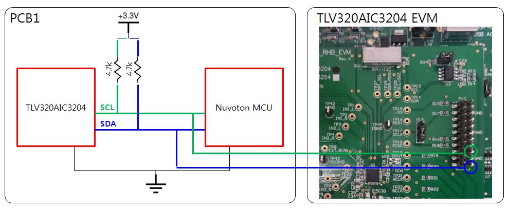
I have a working TLV320AIC3204 PCB and I have been controlling the DSP settings with the MCU.

but I want to setup the whole configuration using EVM GUI first and write the final config into a code at the end.

When I tried to connect the I2C line between the 2 boards, I think it damaged my MCU, my original board is not working properly anymore.

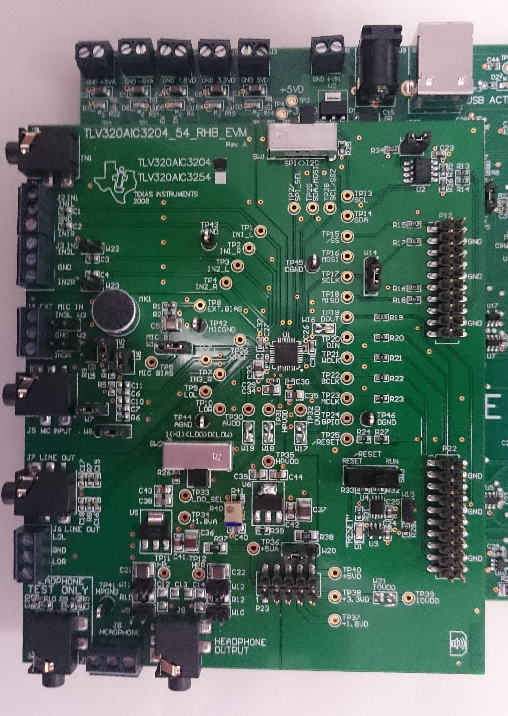
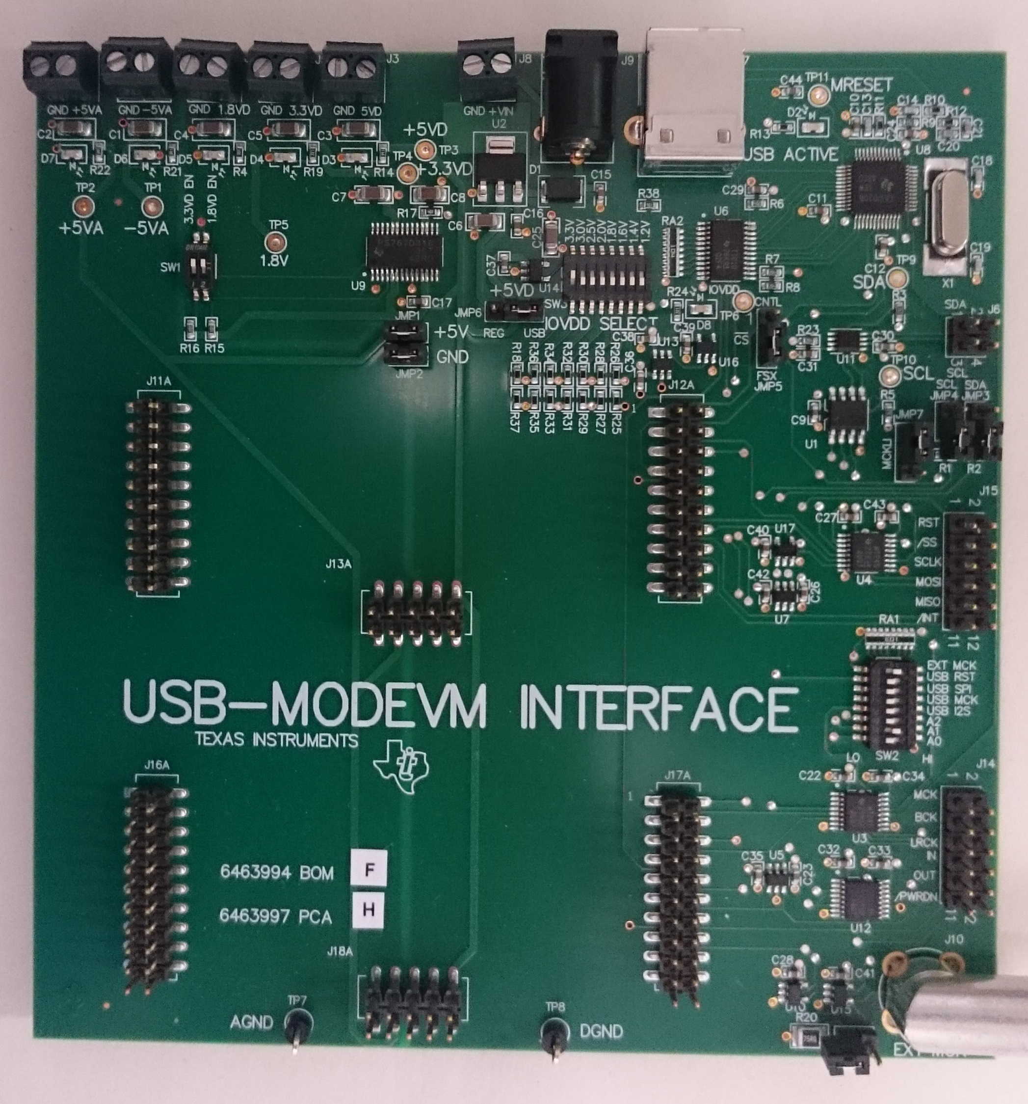
My EVM USB interface is set to "I2C fast" and the board's IOVDD is also 3.3V.

I'm not sure what I connected wrong in the PCB.

Since they are both using 3.3V, I didn't connect the VDD and GND of PCB1 and EVM board.

Is it not possible to use the EVM to control external IC?

  • Hi, Brian,

    Normally, we don't recommend to use the EVM for different purposes. However, you should consider to share the same ground between your application and the EVM. Additionally, you would need to consider that the EVM has a pull-up resistor to IOVDD. For more information, I recommend to take a look at the EVM schematic:

    www.ti.com/.../slau266a.pdf

    Best regards,
    Luis Fernando Rodríguez S.
  • Hello Luis,

    Thanks for your suggestion. The i2c using evm is working perfectly and made my days worth of work to few hours.

    I have an additional question regarding the i2c setting for

    line in-> ADC -> DAC -> line out

    I made it to work on the EVM but it doesn't seem to work in our board.

    The only difference in setting is the clock source. In EVM, it is getting the clock from the MCLK. But in our board, it is coming from I2S bclk made by BT module.

    We checked the bclk is working by BT -> DAC -> line out.

    I also checked the digital loopback option, but still not working.

    I have added my EVM settings , could you check if I am missing anything?

    The analog inputs are IN1R and IN2L.

    AUX ADC setting_Final.pptx

    TLV320AIC3204 Page0 Registers.xlsxTLV320AIC3204 Page1 Registers.xlsx

  • Hello, Brian,

    Effectively, your register configuration is working correctly in the EVM. Do you have additional differences from your board and the EVM?

    www.ti.com/.../slau266a.pdf

    Best regards,
    Luis Fernando Rodríguez S.
  • Hello Luis,

    I finally figured this one out.
    I was using BT module's bclk to run the 3204 codec but when I switched my audio path from "I2S in " to "analog in" there is no clk source for the codec to run on.
    I assumed that once the codec is up and running with any input clk, the clk will not stop until the IC power is shut down. But I found out that I needed to set the PLL Clock Range to High to make my assumption valid.
    So now the codec works with and without the I2S bclk.

    And it's not directly related but I just have a one more question on TLV320AIC3204.
    I am little confused regarding the DAC adaptive filter config register on Page44, Register1.
    I have a adaptive filter coefficients all stored in buffer A but not in B and I don't plan to use Buffer B.
    then would the register value be 0x00000100?
    For Bit1, I tried to find the differences between DAC and control interface accessing 2 different coefficient buffers, but I couldn't find it in the application reference guide.
    For Bit0, I'm not sure what "frame boundary" is and whats the use of this feature.
    I couldn't find the information on Bit1 and Bit2 in any of the documents that I have. (General Datasheet, Design and Config guide, Application reference guide)

    Could you help me to check above 2 bits?

    Thank You
  • Hello, Brian,

    The TLV320AIC3204 Adaptive Filtering Mode consists in coefficients exchange when it is needed. All the processing blocks (and miniDSP if the codec contains it) require of some memory to work. The Adaptive Filtering allows to modify these coefficients while the ADC and DAC are running. It would be a trade-off between memory consumption and coefficients exchange. In adaptive filtering mode, more memory is consumed but it is possible to modify the coefficients while the ADC/DAC is running.

    If you don't require to modify the processing blocks while the ADC and DAC are running, you may disable the adaptive filtering mode (Bit D2). Bit D1 is a flag that indicates which Buffer is in use during the adaptive filtering. Control interface and DAC Coefficient Buffer can be changed to modify the coefficients. Bit D0 controls the Coefficients Buffer change. If this pin is enabled, the Buffer Switch is made at the end of the frame boundary.

    I recommend to take a look at the document below. It contains more information about this feature:

    www.ti.com/.../slaa425d.pdf

    Best regards,
    Luis Fernando Rodríguez S.
  • Hello Luis,

    Now it all make sense. Thanks for the explanation.

    I understood that the "Adaptive filter" was actual feature of turning EQ on and off, not the function to change the EQ on the fly.

    So in my application, which I don't need to switch between several EQs, I don't need this feature.

    I will try to write my coefficient in buffer A when the DAC, ADC is powered down and see if the DSP  picks up the coefficient when DAC turns up.

    Thanks so much.