This thread has been locked.

If you have a related question, please click the "Ask a related question" button in the top right corner. The newly created question will be automatically linked to this question.

TLV320AIC3204EVM-K: Integration TLV320AIC3204EVM-K with external microcontroller STM32F446ME

Part Number: TLV320AIC3204EVM-K
Other Parts Discussed in Thread: TLV320ADC3001

Hello,

Currently I am using onboard mic of this EVM (on the schematic is MK1) and see the resulting signal with my STM32 microcontroller.  So basically the STM32 should trigger the EVM to get signal from onboard mic and send the data continuously through I2S protocol. Here is my interface between the STM32 & the EVM:

__________________________                                            

                      SCL               |                                                    |

-------------------------------------|                                                    |

                     SDA                |                                                    |

-------------------------------------|                                                    |

                                            |                                                    |

                  MCLK                |                                                    |

-------------------------------------|          TLV320AIC3204EVM-K    |

                  BCLK                 |                                                    |

-------------------------------------|                                                    |

                 WCLK                 |                                                    |

-------------------------------------|                                                    |

                 DOUT                 |                                                    |

-------------------------------------|                                                    |

                DGND                 |                                                    |

-------------------------------------| _________________________|

My STM32 using 24 MHz clock, this is used for both MCLK and BCLK pin. No additional component added in between the interface. I refer to this link for the schematic:

www.ti.com/.../slau266

Also, I left the all jumpers and switches condition like the default. According to the schematic, this configuration should be connected to the onboard mic.

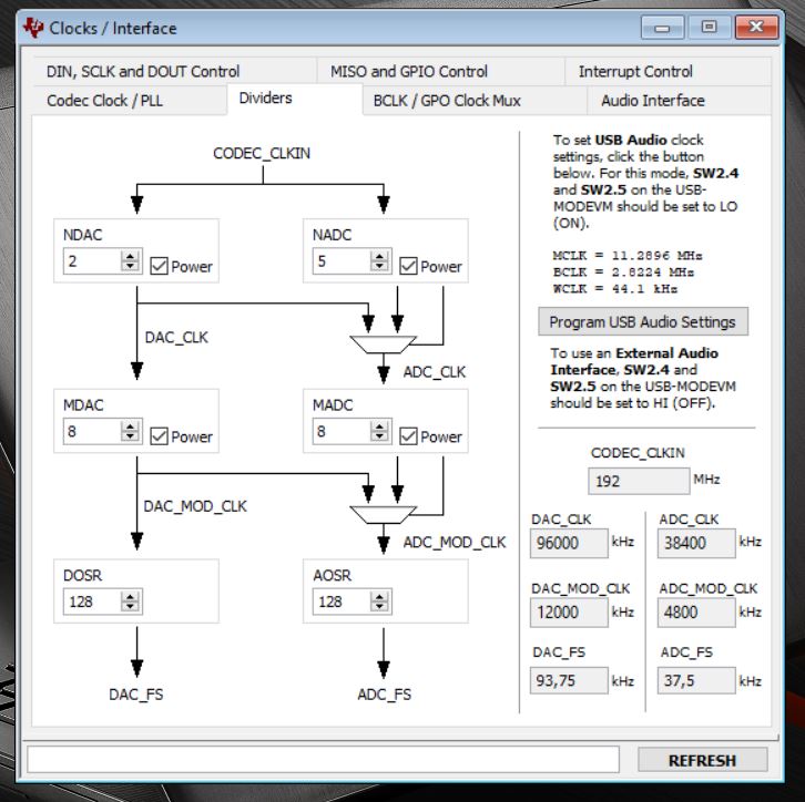
And for the register setting through I2C, I use page 90 of this document  (StereoADCwith48kspsSampleRateandHighPerformance).

www.ti.com/.../slaa557.pdf

I made change for the value of NADC register into 2 (in the example is 1) because I use 24 MHz clock (roughly double the value of clock from the example). As I know from TLV320ADC3001 datasheet I only need to fulfill these conditions:

2.8 MHz < AOSR x ADC_fs < 6.2 MHz

ADC_CLKIN = NADC x MADC x AOSR x ADC_fs

MADC x AOSR / 32 >= RC

However, when I tried this, it seems the STM32 read incorrect values through I2S DOUT pin. The values are random, mostly zero. Even when I give some vibration/sound to the onboard mic, there is no change. Could you help me to find the solution for this issue?

Whether interfacing problem or jumper and switch settings or register setting?

Regards,

Arya

  • Arya, 

    I'm not sure I follow your picture...  can you explain? 

    is the STM32 is using a 3.3V voltage for the Audio Serial interface?  

    Changing the NDAC to 2 rather than 1 will get you close to the right frequency, but if you want to generate a proper Modulator clock,  you will need to use the PLL.  This should work for testing though.  

    SW2 on the USBMODEVM should have USB I2S (SW2-4) set in the HI position (off) 

    SW2 on the USBMODEVM should have USB MCK  (SW2-5) set in the HI position (off)

    have you read back registers to make sure your configuration is in fact getting written?

    best regards,

    -Steve Wilson

  • Sorry for the bad picture, here I give you better picture. Basically I only connect all the required pin (I2C for register setting and I2S for data sampling). The STM32 is using a 3.3V voltage for Audio Serial Interface.

    For PLL clock, could you give me the right document that provide this setting? 

    And for SW2-4 and SW2-5 on the USBMODEVM, I am not sure I can do this from STM32 . What I know is the only SW2 on the EVM board that can be set manually from the hardware.

    Then, I can confirm the register is written correctly by read it back. Another question, do I need to do all register setting like the example 'Stereo ADC with 48ksps Sample Rate and High Performance'?

  • Arya, 

    The TLV320AIC3204EVM-K software has a PLL configuration tool,  this should be able to help you. 

    regarding SW2-4 and SW2-5.  I'm not sure what you mean.  You need to do this manually the switch is a hardware switch.  SW2 has 8 switches on one component. SW2-4 refers to the 4th switch on SW2.  it is labeled "USB I2S",  SW2-5 is labeled "USB MCK"

    best regards,

    -Steve Wilson

  • Hello Steve Wilson,

    Thank you. Now I have installed the software. And I also have figured out where are the SW2-4 and SW2-5 that you mentioned (so far I assumed it is the same as SW2 on the TLV modular board).

    However, I am still confused regarding the PLL setting in the software. Here I give you the pictures of my current setting

    If I use PLL, I have to set SW2-4 and SW2-5 to LO (ON) because I use USB Audio clock (according to the second picture). However, this setting is exactly the opposite of what you said. So which one should I use?

    Furthermore, if I use MCLK and BCLK from external source, can I use these two clocks as the input of PLL? (It seems that I have to define it like the first picture)

    Regards,

    Arya

  • Arya, 

    You said you were hooking this up to an STM32F446ME, and your clocks were connected directly (your pictures)

    This is exactly what I said.  SW2.4 and SW2.5 should be set to "HI" or off

    Regarding the PLL configuration,  my apologies,  I thought the AIC3204-CS software had the PLL configuration tool.  but it appears to be for the AIC3254-CS

    if you download the AIC3254-CS software you can still use this tool:

    This will take into account all of the PLL and Clocking constraints.  

    best regards,

    -Steve Wilson

  • Hello Steve Wilson!

    Yes, that's what I need to understand. So if I want to use external clock, the SW2.4 and SW2.5 should be set to "HI" or off, and for internal clock is vice versa.

    Anyway, thanks for your help! Now I can collect some data from my analog sensor. However, the sampling frequency is still not as I expected. I might need to do some fine tuning for this issue. I'll let you know once I have another question.

    Regards,

    Arya

  • Arya, 

    I"m glad you were able to collect data.  Please let me know if I can be of any help with the sampling rate issue.  The PLL clock tool from the AIC3254-CS software should help you to get the clock settings correct.  just let me know if you continue to have issues.

    -Steve