This thread has been locked.
If you have a related question, please click the "Ask a related question" button in the top right corner. The newly created question will be automatically linked to this question.
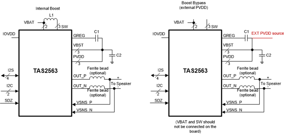
Some applications have voltage regulators or voltage sources with base levels higher than 5.5V. In those cases it may be preferred to use direct connection from external voltage to PVDD instead of using internal boost embedded in TAS2563 and TAS2562.
Best regards,
-Ivan Salazar
Applications Engineer - Low Power Audio & Actuators
Hardware modifications:
For external PVDD voltage, the internal boost will not be used. The Boost Inductor should be simply removed so it is replaced with an open circuit. Then external PVDD voltage can be supplied directly at PVDD pin.
Decoupling capacitors at PVDD pin must remain close to the device for power integrity purposes. Follow the guidelines included in the data sheet and schematic and layout guidelines for component selection.
Power sequence:
When using external PVDD voltage, it is very important to follow the proper power sequence.
Power On Sequence is as below:
Power Off Sequence is in the reverse order, as below:
NOTE: Do NOT Power PVDD while VBAT is Off
NOTE: Minimum PVDD voltage is the same as VBAT. No lower external voltage should be used at any case.
Register settings:
Since internal boost won't be used, it must be disabled. PPC3 currently supports configuration for "always off", however this is not fully disabling the boost.
A simple script can be used to disable the boost, controlling register 0x33 from book 0, page 0. This option will be add to PPC3 in an update as "external PVDD" selection dialog.
w 98 00 00 # Go to page 0
w 98 7f 00 # Go to book 0
w 98 00 00 # Go to page 0
w 98 33 d4 # Select Boost always off and Disable the Boost