This thread has been locked.

If you have a related question, please click the "Ask a related question" button in the top right corner. The newly created question will be automatically linked to this question.

TAS2563: Linux integration with PVDD only: no sound

Part Number: TAS2563
Other Parts Discussed in Thread: TAS2780

Tool/software:

Hi,

I'm currently integrating the amplifier in a mono speaker configuration in an embedded Linux project.

The hardware is set up to use PVDD only (no VBAT) as described in this FAQ.

Schematics:

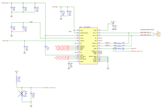
PVBUS (connected to PVDD and VBST) is configurable, we've set it to 9V.

For the software I grabbed the latest driver from the for-next branch of https://git.kernel.org/pub/scm/linux/kernel/git/broonie/sound.git. As far as I understand, that one should run even without having DSP parameters configured. We are using kernel 5.10, so I had to make a few minor changes to make it compile.

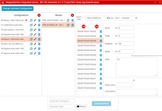
I created the firmware binary with the regbin tool from https://git.ti.com/cgit/tas2781-linux-drivers/tas2781-linux-driver/tree/regbin/toolset together with the contained JSON file tas2563-1amp-reg.json and compiled it into the  kernel using CONFIG_EXTRA_FIRMWARE. 

As we don't use VBAT, I added a register setting book 0x00, page 0x00, register 0x33, value 0xc4 to every power up configuration before writing the bin file.

The driver complains about the coef.bin file not being preset:

# dmesg | grep tas2
[ 0.706546] tasdev-codec 2-004f: Direct firmware load for tas2563_coef.bin failed with error -2
[ 0.716538] tasdev-codec 2-004f: tasdevice_dsp_parser: load tas2563_coef.bin error
[ 0.724327] tasdev-codec 2-004f: dspfw load tas2563_coef.bin error

but I think it loads anyways because I can see the profile selection in amixer:

# amixer contents
numid=2,iface=MIXER,name='DMIC High Pass Filter1 Switch'
; type=BOOLEAN,access=rw------,values=1
: values=on
numid=3,iface=MIXER,name='DMIC High Pass Filter2 Switch'
; type=BOOLEAN,access=rw------,values=1
: values=on
numid=4,iface=MIXER,name='DMIC Low Pass Filter Switch'
; type=BOOLEAN,access=rw------,values=1
: values=on
numid=5,iface=MIXER,name='DMIC SW_LR Switch'
; type=BOOLEAN,access=rw------,values=1
: values=off
numid=1,iface=MIXER,name='DMIC Volume'
; type=INTEGER,access=rw---R--,values=1,min=0,max=31,step=0
: values=15
| dBscale-min=0.00dB,step=3.00dB,mute=0


.... [ several mux config settings ] ....

numid=8,iface=MIXER,name='Mixer0 LR_MIX Switch'
; type=BOOLEAN,access=rw------,values=1
: values=off
numid=9,iface=MIXER,name='Mixer0 MIX_MODE Option'
; type=ENUMERATED,access=rw------,values=1,items=4
; Item #0 'Linear weighted plus'
; Item #1 'Average'
; Item #2 'Clamping'
; Item #3 'Nonlinear Distort'
: values=1
numid=6,iface=MIXER,name='Speaker Force Firmware Load'
; type=BOOLEAN,access=rw------,values=1
: values=off
numid=7,iface=MIXER,name='Speaker Profile Id'
; type=INTEGER,access=rw------,values=1,min=0,max=7,step=0
: values=0
numid=10,iface=MIXER,name='baic1_fmt'
; type=ENUMERATED,access=rw------,values=1,items=11
; Item #0 'PCMA'
; Item #1 'PCMB'
; Item #2 'DSPA'
; Item #3 'DSPB'
; Item #4 'TDM1A'
; Item #5 'TDM1B'
; Item #6 'TDM2A'
; Item #7 'TDM2B'
; Item #8 'I2S'
; Item #9 'LEFT'
; Item #10 'RIGHT'
: values=8

aplay does not complain:

# aplay -l
**** List of PLAYBACK Hardware Devices ****
card 0: dv20 [d_v20], device 0: DMA1 playback (*) []
Subdevices: 0/1
Subdevice #0: subdevice #0


# aplay /data/sound/test.wav

Playing WAVE '/data/audio/test.wav' : Signed 16 bit Little Endian, Rate 44100 Hz, Mono
However, no sound comes out of the speaker.
Here is a register dump (while aplay is running):
# i2cdump -y -f -r 0x00-0x7F 2 0x4f
No size specified (using byte-data access)
0 1 2 3 4 5 6 7 8 9 a b c d e f 0123456789abcdef
00: 00 00 00 20 c6 22 13 02 00 10 f1 46 44 04 05 06 ... ?"??.??FD???
10: 07 14 12 76 01 2e 60 0e 0c 00 fc a6 df ff ff 04 ???v?.`??.???..?
20: 00 00 80 00 04 00 22 80 00 80 00 00 00 00 00 a2 ..?.?."?.?.....?
30: 99 40 80 c4 4b 74 03 00 0d 0c be 58 68 08 10 00 ?@??Kt?.???Xh??.
40: 76 41 d8 c0 10 21 00 b4 ac 00 00 00 00 00 00 00 vA???!.??.......
50: 00 00 00 00 00 00 00 00 00 00 00 00 00 00 00 00 ................
60: 00 00 00 00 00 00 00 00 00 00 00 00 00 00 00 00 ................
70: 00 00 00 f0 00 0f 00 00 80 00 00 00 00 10 7b 00 ...?.?..?....?{.


What should I try next?

Thanks,

  Stephan

  • Hi Stephan, 

    I notice that the register 0x08 has RX_SCFG set to "00b = Mono with time slot equal to I2C address offset". meaning the address 0x4F device is trying to play data from TDM time slot 4. if you are only playing a mono file which is having data in slot 0 then the device may be pulling from a slot which has no data. can you try setting RX_SCFG = 01b?

    Regards,
    Arthur

  • Hi Arthur,

    thanks for the suggestion. As far as I understand the program number 4 should support stereo downmix:

    When I use that (selecting it via amixer) I get this register dump:

    # i2cdump -y -f -r 0x00-0x7F 2 0x4f
    No size specified (using byte-data access)
         0  1  2  3  4  5  6  7  8  9  a  b  c  d  e  f 0123456789abcdef
    00: 00 00 00 20 c6 22 09 02 70 10 13 40 42 04 05 06 ... ?"??p??@B???
    10: 07 14 12 76 01 2e 60 0e 0c 00 fc a6 df ff ff 00 ???v?.`??.???...
    20: 00 00 80 00 04 00 22 80 00 80 00 00 00 00 00 a2 ..?.?."?.?.....?
    30: 99 40 80 c4 4b 74 0c 00 0d 0c be 58 68 08 10 00 ?@??Kt?.???Xh??.
    40: 76 41 d8 c0 10 21 00 b4 ac 00 00 00 00 00 00 00 vA???!.??.......
    50: 00 00 00 00 00 00 00 00 00 00 00 00 00 00 00 00 ................
    60: 00 00 00 00 00 00 00 00 00 00 00 00 00 00 00 00 ................
    70: 00 00 00 f0 00 0f 00 00 80 00 00 00 00 10 13 00 ...?.?..?....??.

  • I was able to probe the SBCLK1, FSYNC and SDIN1 pins and I can see that data is flowing to the chip while aplay is running. OUT_P and OUT_N remain silent.

  • Hi Stephan, 

    Can you please share details about your clocks? such as the BCLK/FSYNC frequencies and the slot and word width?

    in both the register dumps you are sharing i can see the device is showing reg 0x24 = 0x04 TDM clock error.

    Regards,
    Arthur

  • Hi Arthur,

    I am unable to reproduce the 0x24 = 0x04 TDM clock error now. Maybe that was a latched interrupt from experiments before when I was switching the programs during playback.

    This is a "clean" register dump before playback:

    # i2cdump -y -f -r 0x00-0x7F 2 0x4F
    No size specified (using byte-data access)
         0  1  2  3  4  5  6  7  8  9  a  b  c  d  e  f 0123456789abcdef
    00: 00 00 0e 20 c6 22 09 02 4a 10 13 02 00 04 05 06 ..? ?"??J???.???
    10: 07 7f 12 76 01 2e 60 0e 0c 00 fc a6 df ff ff 00 ???v?.`??.???...
    20: 00 00 00 00 00 00 00 00 00 00 00 00 00 00 00 00 ................
    30: 19 40 81 34 4b 74 0c 00 0d 0c be 58 68 08 10 00 ?@?4Kt?.???Xh??.
    40: 76 41 00 c0 10 21 00 00 2c 00 00 00 00 00 00 00 vA.??!..,.......
    50: 00 00 00 00 00 00 00 00 00 00 00 00 00 00 00 00 ................
    60: 00 00 00 00 00 00 00 00 00 00 00 00 00 00 00 00 ................
    70: 00 00 00 f0 00 0f 00 00 80 00 00 00 00 10 00 00 ...?.?..?....?..

    During playback:

    # i2cdump -y -f -r 0x00-0x7F 2 0x4F
    No size specified (using byte-data access)
         0  1  2  3  4  5  6  7  8  9  a  b  c  d  e  f 0123456789abcdef
    00: 00 00 00 20 c6 22 09 02 70 10 13 40 42 04 05 06 ... ?"??p??@B???
    10: 07 14 12 76 01 2e 60 0e 0c 00 fc a6 df ff ff 00 ???v?.`??.???...
    20: 00 00 80 00 00 00 32 80 00 40 00 00 00 00 00 a3 ..?...2?.@.....?
    30: 99 40 80 c4 4b 74 00 00 0d 0c be 58 68 08 10 00 ?@??Kt..???Xh??.
    40: 76 41 d8 c0 10 21 00 91 2c 00 00 00 00 00 00 00 vA???!.?,.......
    50: 00 00 00 00 00 00 00 00 00 00 00 00 00 00 00 00 ................
    60: 00 00 00 00 00 00 00 00 00 00 00 00 00 00 00 00 ................
    70: 00 00 00 f0 00 0f 00 00 80 00 00 00 00 10 4f 00 ...?.?..?....?O.

  • [ 85.607703] tasdev-codec 2-004f: tasdevice_hw_params: sample rate = 44100
    [ 85.614835] tasdev-codec 2-004f: tasdevice_hw_params: slot width = 16
    [ 85.621584] tasdev-codec 2-004f: tasdevice_hw_params: bclk rate = 1411200

    I measured the frequency on the BCLK and FSYNC pins and they match what the driver says.

    Where can I find the word width?

  • Hi Stephan,

    Word width is just the width of the data inside the data slot. i.e. how many bits of each slot contain data.

    I do not see anything of concern with these settings.

    I would like to see if we can get the device to power up and play with some very simple I2C Configuration. can you try running the below script to see if the device can playback?

    w 4f 00 00
    w 4f 7f 00
    w 4f 00 00
    w 4f 01 01
    w 4f 33 c4
    w 4f 02 00

    Regards,

    Arthur

  • Hi Stephan, 

    Can we also check the VBAT supply during the initialization, with the full initialization? one of the interrupt flags coming is from a VBAT POR. can we make sure the supply is not dropping during the initalization?

    would also be good to double check all of the power supllies as well

    Regards,
    Arthur

  • I think we might have misunderstood the need on VBAT. In our application we changed from a TAS2780 to the TAS2563. The former had a power mode where VBAT would be generated internally but reading this application note again it seems the TAS2563 needs VBAT even if we use the "external PVDD configuration". Is that correct?

  • (we use an external power supply and no battery, forgot to mention that in the original post)

  • Hi Steven, yes that is correct VBAT will needed... I hope you do not need to re-spin your design. I see you have 3.3V available. are you able to connect this rail to the VBAT pin?

    Regards,
    Arthur

  • We are making a rework now connecting 3V3 to VBAT.

    We'll need to spin the board to make that permanent

    Are you seeing any other issue with the schematics?

    Thanks for your help!

  • Hi Stephan, 

    No I do not see other issues in the design - apologies for not noticing there was no external connection to VBAT

    Regards,

    Arthur