This thread has been locked.

If you have a related question, please click the "Ask a related question" button in the top right corner. The newly created question will be automatically linked to this question.

LMX2487E: Not able to get the lock detect

Part Number: LMX2487E
Other Parts Discussed in Thread: USB2ANY, CODELOADER

Hello, we have integrated an LMX2487E as the PLL synthesizer and we have connected the USB2ANY device to the  CLK, DATA, and LE and the ground of the Microwire interface (CE is pulled to high always). We have provided a very high precision 40Mhz OCXO (ECS-2522) and verified its present at the chip input. We also provided the proper loop filter components that have worked for other design and has been qualified for this design. 

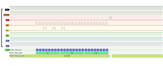
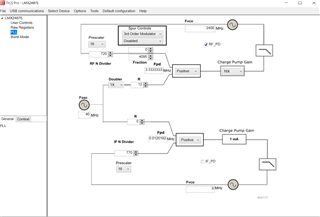
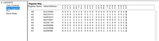
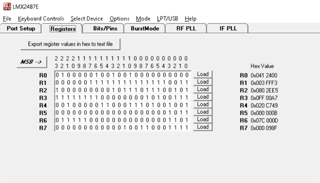
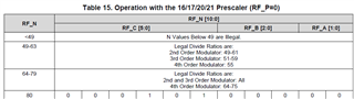
I am using TICS Pro to set register values. But repeated attempt at programming the chip has rendered into failure. By failure, I mean the lock detect (pin 12) staying low no matter what I try, I don't know of any other way I can debug this at the moment so I need some help. I have tried default register settings as well as targeted register settings that makes sense, not using the fractional divider for simplicity. only using RF PD, no clock doubler, RF N divider is 720, My target frequency is ultimately above 4 Ghz but currently I am testing 2.4 Ghz. Charge pump gain set to 16. R divider set to 12 resulting in 3.333333Mhz FPD. here are some screenshots. The first one is the SPI communication trace. Second one is the loop parameters, The third is all the register values. At this point I am stuck. Any help from an expert would be much appreciated. Thank you.

Ratin

Update 1: Probed the charge pump output and its always sitting at zero. 

Update 2: Used a second part to rule out any issue with the first chip, the same result. 

Update 3: Looks like TICs Pro software has an issue of programming the MUX register value to configure lock detect, it only allows R4 to be set with odd numbers, even numbers make the register value red (???)

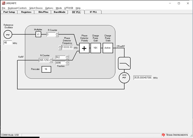
               The other app Code Loader 4 has options to select The Mux register content with a pull down   however it doesn't change the actual value of R4 register.


  • Hi Ratin,

    I recently found out that TICS Pro generates the wrong RF_N register value, I am fixing this bug right now. In the mean time, please use CodeLoader4 to program the EVM.

    BTW, 2400MHz is not a valid frequency to the RF PLL, the min. frequency is 3000MHz.

  • Hi Noel, Thanks a lot for your reply, appreciate it. The issue was indeed the frequency range I was setting the pll with. I got the Lock detect signal to come on (it seems kind of low at 0.75 v),  working with CodeLoader with above 4 Ghz range but I do have a question, when I use the app, it only sends two registers, R0 and  R5, even though I selected all registers in the Bits/Pins tab Access pull down. Is that a bug? How does the chip know that these two particular registers are getting sent? 

    Thanks,

    Ratin

    Update: Actually I am not sure if the 0.7v that I am seeing is just a fluke or not cause I dont get the RF frequency coming out of the VCO side. As far as  Tics Pro, looks like I found another bug, its not letting me choose 32 prescaler when I am setting 4.45 Ghz, but 32 prescaler is a must on the CodeLoader4 for anything above 4 ghz

    Update 2: I am finally seeing the lock detect coming on when code Loader 4 is being used, however no RF out, probably something on my side.

  • Hi Ratin,

    Right, the prescalar is another bug in TICS Pro, I will fix this one as well. What was your R4, MUX, setting? If a push-pull output is selected, then a logic HIGH should be 2.5V. If an open-drain output is selected, then an external pull-up resistor is needed in order to see the signal coming out from the Ftest/LD pin.

    No matter which tool you use, you need to press Ctrl + L keys to load all the registers once. If you change one of the configurations, the tool will calculate which register value is needed to update and will update that register only.

    Please note, if you use active filter, you need to select the proper phase detector polarity to match the characteristic of the active filter.

  • Hi Noel, Mux is set to "RF Digital LD PP" so yes its configured as push-pull. Yesterday I was seeing the LD at 3V buts very flaky and stayed at 3 v even when I started programming impossible frequencies,  And even though it was there, the RF was missing on the VCO. So I think its not working as expected. And then it disappeared and then never saw it again. I don't think we are using active filter, we are not changing the loop behavior by any external input, the only input to the VCO is Vtune and we sort of followed the cascaded R/C filter on the feedback path as suggested in the datasheet. The R/C components were used on another design which was working at 2.4 Ghz range so we might need to see how much of a change needed for our new range (4-5ghz), an engineer is looking into that right now.    

  • Hi Ratin,

    You can use PLL Sim to design the loop filter.

  • Thank you, yes we have been looking at that and found some anomaly. Will report back either way. 

  • Hi Noel, Turned out it was our issue, a technician wrongfully omitted a cap which was in the feedback path. Also changing the filter components helped. Thanks for your suggestion.

    On a similar note, Do you know why the register value doesn't correspond to the Rf_N when Prescaler 16 is used on the CodeLoader4? In the following scenario I try to program the second PLL with an output freq 3.535 Ghz. The N Counter is calculated correctly (265) to match the PFD of 1.33333333 Mhz  (roughly) but the R0 content is 0x412400 which corresponds to 521. Is it because of the pre-scaler change form 32 to 16?


  • Hi Ratin,

    The register maps is confusing, RF_N does not represent the PLL N-divider value. In below Table, the left most column should be re-named to something like RF PLL N. 

  • Hi Noel, Gotcha but it still doesn't makes sense, may be I am missing something. If we back calculate to find the PLL_N divider from RF_N, With 0x412400 being the R0 content, I get

    RF_N= 01000001001b (11 bits)

    RF_C=010000b (6 bits)

    RF_B=010b (3 bits)

    RF_A=01b (2 bits)

    RF_P=0 (16 bit pre-scaler)

    N =  RF_P × RF_C + 4 × RF_B + RF_A = 0 x1610 + 4*210  +1 = 9 

    Am I missing anything? The fractional numerator seems to be fine.

    Thanks

    Ratin 

  • Hi Ratin,

    PLL N <49 is not allowed. 

    From your codeloader screen shot, PLL N = 265 and P = 16.

    For quadruple modulus prescaler:

    RF_C = Int ( PLL N / P) = 16

    RF_A = N Mod 4 = 1

    RF_B = Int [(PLL N - P*C)/4] = 2

  • Hi Noel, 

    Thanks for clarifying that, the equation as written on page 26 N = RF_P × RF_C + 4 × RF_B + RF_A is very confusing. According to table 19 on page 29, RF_P is 0 for pre-scaler 16, so that's what confused the heck out of me. Whoever wrote the datasheet should use another term like  N = Prescaler_Int × RF_C + 4 × RF_B + RF_A.

    BTW what is C above? Are these derivations mentioned somewhere in app notes or another manual? 

    Thanks,

    Ratin

  • Thanks, I had this document but thought these variables were parts specific. So C in your  RF_B = Int [(PLL N - P*C)/4] = 2 should be RF_C. What happened to the -a term in the numerator of the equation? 

  • Hi Ratin,

    That one shown the complete relationship between A, B, C and N. 

    The definitions of A, B and C are given in my previous thread. Keep in mind that A, B and C are counters. When counter A is finished, counter B takes over. Counter C will step in once counter B is over. As a result, you won't see A in the definition of B. Similarly, there is no A and B component in the definition of C.