This thread has been locked.

If you have a related question, please click the "Ask a related question" button in the top right corner. The newly created question will be automatically linked to this question.

LMK05028: Programming Procedure

Part Number: LMK05028

Hi team,

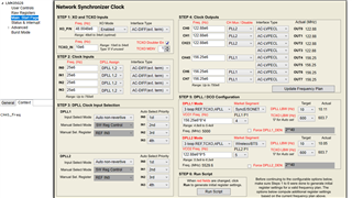
Customer plans to use LMK05028 as  Hard pin mode by pulling high at HW_SW_CTRL pin.

1. After start-up, does customer need to write all register map generated by TICS Pro, right?

2. To change the output frequency, what is the recommended procedure?

3. When changing the output frequency, is it okay that change only the corresponding registers? Or all register map should be overwrote?

Best regards,

Hideki

  • Hideki-san,

    1. After start-up, the customer either loads a saved configuration or uses the wizard with steps 1-6.

    2. Ideally you use the "wizard". If the configuration of DPLL/APLLs is already done with the wizard then you can also change the output divider manually. This can only change the output to related frequencies to the VCO. You may want to assert a SYNC again to have the outputs aligned again.

    3. see above.

    regards,

    Julian

  • Hi Julian,

    What did you mean to use "wizard"? I know a recommendation around configuration is to use TICS Pro. To think a real application, there are just a communication between processor and LMK05028. I'm asking how to do those.

    Best regards,

    Hideki

  • Hideki-san,

    sorry, the Wizard is that Start page that I show in the picture from my last post.

    Right, in real application, you need to write all registers after start up. Then, as mentioned earlier, you can manually change the output dividers without the need to rewrite everything.

    regards,

    Julian

  • Hi Julian,

    I don't understand well about the second and third question from my first post.

    2. To change the output frequency, what is the recommended procedure?

    I'm trying to ask in other words, is there any hardware control or software control for example, disabling the output at first, then writing other frequency setting (= dividers value setting)  and something like that.

    you can manually change the output dividers without the need to rewrite everything.

    I understand. 

    Is there any way to extract and get the difference between the register of the first setting and the register after the change in TICS Pro?
    If not, do I need to compare them all manually?

    Best reagrds,

    Hideki

  • Hideki-san,

    an easy way to monitor the register changes is to look at the status bar. All register writes are logged in there.

    There is no control when you change the output divider. If a new divider value is written in the register the frequency will change immediately. Disabling the output first, then updating the divider and followed by enabling the output again is a good approach.

    regards,

    Julian

  • Hi Julian,

    Let me bring back customer feedback.

    1. Understood all register must be written. I think read-only registers do not require to be set. What is the best way to pick only write register?

    2. 3. Customer says LMK05028 doesn't change the output frequency unless they do RESET_SW even if the AUTOSTART register is high.

    Is the below sequence correct?

    Write new divider values

    -> Pull R12 bit 7 (RESET_SW) to HIGH

    -> Wait (is there any specification?)

    -> Pull R12 bit 7 (RESET_SW) to LOW

    -> Start output

    Best regards,

    Hideki

  • Hello Hideki-san,

    At this point, we don't have a simple way to separate the read only from the write registers to generate a minimum write sequence simply, however the register documentation contains this information for each register.  For example:

    On the "Main: Start Page" we have added buttons to generate register sets for DPLLx, and DPLLx + outputs.

    Perhaps you could meet your requirements for knowing which registers to program by using DPLLx + outputs and examining the resulting text file output.  It has comments to see what area is changing.  Note it also includes masks so you don't impact other fields related to other items.

    Your sequence would work, to make a change and then do a reset, however...  it is my understanding it is not required to do a full RESET_SW which changing this values, you could reset only APLL1/DPLL1 for example:

    # APLL1/DPLL1 Reset
    R677    0x02a501     &     0x000001
    R677    0x02a500     &     0x000001

    You can also use the first end ending lines to power down outputs while changing... Note this is sensitive to the current configuration depending on how many outputs from from DPLLx (DPLL1 in this example).

    # First power down the outputs changing
    R51    0x00333f     &     0x00003f

    # Last power up the outputs
    R51    0x00330f     &     0x00003f

    73,
    Timothy

  • Hi Timothy

    As conclusion, please confirm procedure below are all correct when programming a new configuration.

    1. Write 3fh to R51 to disable output

    2. Write all register which have to be changed for updated configuration.

    3. Write 1b to R677[1] to assert soft-reset at PLL2

    4. Write 0b to R677[1] to exit soft-reset

    5. Write 0b to R51[wanted channel] to enable output channel

    Best regards,

    Hideki

  • Hello Hideki-san,

    Yes, for making changes to PLL2, this procedure is correct.  However you can write '1' to disable only outputs driven by PLL2.  Doesn't have to be 0x3f.

    73,
    Timothy