Because of the holidays, TI E2E™ design support forum responses will be delayed from Dec. 25 through Jan. 2. Thank you for your patience.

This thread has been locked.

If you have a related question, please click the "Ask a related question" button in the top right corner. The newly created question will be automatically linked to this question.

CDC421A156: Not differential output.

Part Number: CDC421A156

I have a design with the mentioned clock generator and we are having no differential output. I would like to have some support on what the issue could be.

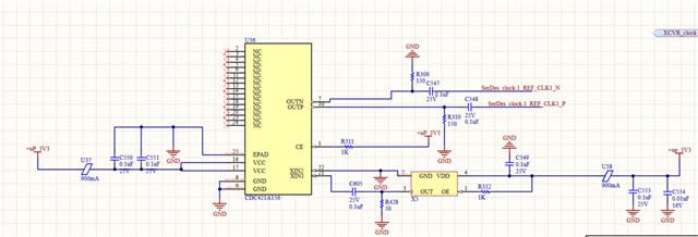
The design is the following:

And the internal circuit to what it is connected to is this:

The clock input reference is 31.25MHz and supplies and CE are okey.

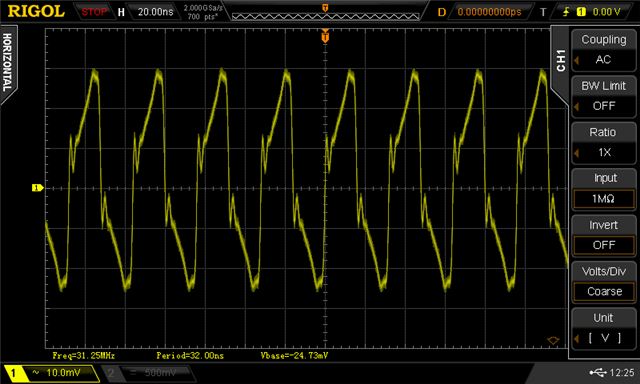
I have measured the input clock and I have checked an offset of 3V. Could this be the issue?

Thankyou in advance!

  • Hi,

    I could be observing 2 causes:

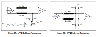
    1. For LVPECL output, 50ohm termination at receiver side should be after series cap. In current configuration, 150ohm and 50ohm are in parallel and it will affect overall required termination for LVPECL output.

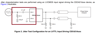
    2. Is X5 crystal or LVCMOS driver? If crystal, then follow its termination option from crystal datasheet. For LVCMOS input, follow below circuit.

    Thanks!

    Regards,

    Ajeet Pal 

  • Thank you so much Ajeet Pal for your answer.

    1. I can not modified the internal circuitry of the receiver, so the 50ohms terminations before the series cap can not be modified. What could I do here? to add a series cap in my external circuit? I mean between the 150 termination resistors and the receiver input. 

    2. Yes, it is a LVCMOS input, I would try a rework to include that circuitry. The value of the serie cap (0.1pF) makes me think that it only represents the capacitance of the line. But you mean that I should add the caps and the resistors, right?

    3. Do I need any of the following external termination circuit?

    Thank you again in advance.

  • Hi,

    1. I can not modified the internal circuitry of the receiver, so the 50ohms terminations before the series cap can not be modified. What could I do here? to add a series cap in my external circuit? I mean between the 150 termination resistors and the receiver input. 

    Yes, you can place series caps between the 150 termination resistors and the receiver input. 

    2. Yes, it is a LVCMOS input, I would try a rework to include that circuitry. The value of the serie cap (0.1pF) makes me think that it only represents the capacitance of the line. But you mean that I should add the caps and the resistors, right?

    Series cap is needed to isolate the common mode level between input signal and device input pin in AC coupled mode. Shunt 50ohm is to provide the required input impedance for input signal.

    3. Do I need any of the following external termination circuit?

    For LVPECL output, 150ohm shunt already present. Hence no need to have any external circuit except series capacitor.

    Thanks!

    Regards,

    Ajeet Pal

  • Hi Ajeet Pal,

    I have implemented both suggested reworks but the clock generator is still not working. I have now the shown design implemented:

    Any other ideas?

    Thank you in advance.

    Paula

  • Hi Paula,

    Now the schematic looks good, except series cap (100pF) missing with shunt resistor (R428) at XIN1 input. Try to keep the series cap and see the performance. Also try to see the waveform at the input of XIN1 pin.

    What is the output you are getting in this configuration? May be can verify the supplies also in circuit.

    Thanks!

    Regards,

    Ajeet Pal

  • Hi Ajeet Pal,

    I would try to add that series cap.

    I am having no output (just noise with 10mVpp).

    The input clock reference is not the best, but I have no idea on why.

    I have already checked the supplies and enables and everything is okey. No special sequence is required, right? I have read in some other tickets in this forum, that the supply of the oscillator should be stable before supplying the clock generator, but that was related to a different PN, the datasheet of the device that I am using does not specify any specific sequence.

    Thank you again,

    regards.

  • Hello again, I have fixed the issue. It was with the oscillator, the connection was wrong. I was connecting what I though it was the output of the oscillator to the supply pin. 

    Now everything is working, even without the series capacitor and shunt resistor at the input.

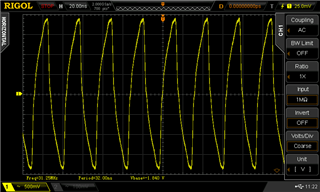
    The input looks much better now: 

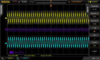
    And I have the proper output:

    Thankyou for all your help and ideas.

    Regards,

    Paula