This thread has been locked.

If you have a related question, please click the "Ask a related question" button in the top right corner. The newly created question will be automatically linked to this question.

LMK04828BEVM: not locking to jittery clock

Part Number: LMK04828BEVM
Other Parts Discussed in Thread: LMX2572, LMK04828

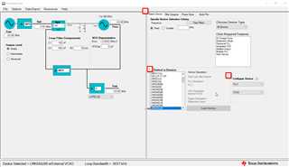
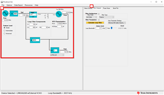
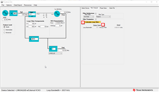
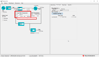
We are working with a LMK04828B board and TICSpro

We are trying to generate a 1 GHz clock using a 25 MHz input (CLKin1). 

1. In our first configuration we use an AWG to generate the 25 MHz, in this case the CLKin1 is very low jitter, and we can see that the board locks to it (both PLL1 and PLL2 LEDs are ON). Monitoring on the scope we see that the 25 MHz and the 1 GHz are locked to each other.

2. In the second configuration, we use an electronic board to generate the 25 MHz (CLKin1). The jitter of the 25 MHz generated by our board is higher than when generated with an AWG. In this case we are unable to lock the 1 GHz to the CLKin1. The PLL1 LED is OFF, but the PLL2 LED is ON.

 3. As a simple test, we also use a PLL+VCO model LMX2572 to generate 1GHz using the jittery 25 MHz: this configuration works without problem and the 1GHz generated clock is locket to the jittery 25 MHz input clock.

We expected the jitter cleaner feature of the LMK04828B to help it lock better. However, with the jittery 25 MHz, we could not find what settings combination would let the LMK04828B generate a 1 GHz locked to the 25 MHz CLKin1. Can you please explain why and help us debug it?


Kind regards

  • 25MHz_CLKin1.tcs

    Attached, the TICSPro configuration file

  • Hello Taofiq,

    Since you are using the EVM and assuming you are using the same configuration file you provided for both reference signals, you are seeing your system go out of lock because of an unstable loop filter. Because your first reference is clean, an unstable loop filter won't necessarily cause the LMK04828 to go out of lock. However, for a dirtier reference, you would want a loop filter with a higher phase margin (in other words a more stable loop filter) to clean it better and lock your PLLs.

    You can use TI's tool, PLLatinum Sim, to calculate the best loop filter for your design. Note that the default EVM values are already preloaded into the LMK04828B PLLatinum Sim and all you have to do is change your phase detector frequency (Fpd) for it to calculate your optimal loop filter. Hope this helps!

    Good Luck,

    Andrea

  • Hi Andrea,

    Thanks for your reply. I confirm (as I wrote in the post) that with a clean reference I have no problem locking. However the reference we want to use is indeed dirtier.

    It is still not clear to me how and where to set the phase margin in TICs Pro?

    Do you think that I only need to change the one of  PLL1? 

  • Hello Taofiq,

    Let me re-explain what the problem to your system seems to be. For the PLL to establish lock, the loop filter must be stable, especially when dealing with a dirty reference (i.e the phase margin of the loop filter must be above 40 degrees). You are seen lock in the first set-up because with a cleaner reference, lock can still be established even with an unstable loop filter. If this explanation does not make sense, please let me know which part of this explanation does not make sense and I can further help you with it.

    To fix your problem, you need to redesign a loop filter on the EVM. Note that the EVM already has a loop filter design on it, so you would have to unsolder teh default components from the board and re-solder new ones to ensure you achieve lock.

    To determine what the new components for your loop filter will be you need to use PLLatinum Sim (link to download here), which is another tool (not TICS Pro) that will help you to calculate the loop filter. The parameters that matter for current calculation of the loop filter are the pase detector frequency (Fpd), charge pump current (Kpd), loop filter components, Kvco, and output frequency. When inputting those components into PLLatinum Sim tool, the phase margin comes out to be around 27°, which makes your loop filter unstable (as explained above). To fix that issue:

    1) Select the device you are using (in this case LMK04828B) in the (A) "Select Device" tab under (B) "Select a Device" and that you are choosing the correct PLL with the correct VCO under (C) "Configure Device" (in this case we are checking the set-up for PLL1 and we are using an external VCXO).

    2) Go to the (A) "Filter Design" tab and (B) make sure your PLL settings (i.e Fosc, dividers, Fpd, Kpd, Kvco & Fvco) are correct and match your TICS Pro set up

    3) (A) Tick the checkbox under "Auto" for Loop Bandwidth and (B) click on "Calculate Loop Filter" button.

    4) Let the tool run, after a few seconds you should see your new values for the loop filter that should lock your PLL.

    The components from the screenshot above should be the ones you use for your new loop filter since I ran the example with your configuration. Hope this helps. Also I have attached the .sim file for you to load it into PLLatinum Sim once you download the tool.

    https://e2e.ti.com/cfs-file/__key/communityserver-discussions-components-files/48/E2E_5F00_NotLockingJitteryClock.sim

    Hope this helps.

    Good luck,

    Andrea