Because of the holidays, TI E2E™ design support forum responses will be delayed from Dec. 25 through Jan. 2. Thank you for your patience.

This thread has been locked.

If you have a related question, please click the "Ask a related question" button in the top right corner. The newly created question will be automatically linked to this question.

LMK5B33414: LMK5C33414 ; FAIL SAFE CONDITION

Part Number: LMK5B33414
Other Parts Discussed in Thread: AM6412, LMK5C33414

Hi Team,

We are using LMK5C33414 in our latest design along with AM6412.

SO LMK is programming by AM6412 through SPI. and also its PD# pin is connecting to GPIO of AM6412.

So as per AM6412 experts opinion we have followed a power sequence as

AM6412 IC will powered up >> LMK IC will powered up. Is there any issue for LMK IC that it will have the SPI signals and PD# GPIO signal before the clock IC getting supply.?

Please note that XO power supply will turned on before clock VCC as per datasheet.

  • Hi Sreejitha,

    I have paged our device experts.

    Best,

    Evan Su

  • Hi Sreejitha,

    Our experts are busy until next week, but I looked at this today and have some information. When the LMK is powered off (VCC = 0V), the logic input pins are only tolerant of -0.3V to +0.3V according to the electrical specifications. Digital logic levels used for SPI/I2C are usually 1.8V or 3.3V. I don't think the device will be critically affected by occasional SPI or GPIO inputs while it is off, but there is some risk of damage or reduced product lifespan if this happens continuously over time. I can ask our design team for confirmation if our device experts aren't able to get back to you.

    Best,

    Evan Su

  • Hi Evan,

    After initializing AM6412 kernel only , AM6412 SPI communication with LMK5C33414 will start. And LMK will turned on after AM6412 booting  . So hope it will be fine.

  • Hi Sreejitha,

    I am not familiar with the AM6412 but if it is possible to power on the AM6412 but delay the kernel initialization until after the LMK5C33414 starts up, that would be the ideal case. The behavior of the SPI communication could also be considered, if the interface is active but the AM6412 does not immediately start issuing write/read commands then that gives more time to the LMK to finish booting.

    I will wait some more for our experts to opine before following up myself.

    Best,

    Evan Su

  • Hi

    We can do one thing. We will follow the below sequence.

    1. AM6412 processor powering and u-boot

    2.CLK_3V3_EN from GPIO

    3. AM6412-LMK   SPI Kernel running

    Kindly check this approach to achieve AM6412 and LMK sequencing

     Hope there is no issue for PD# pin is pulled up to a voltage which is turning on before LMK supply.

  • Hi Sreejitha,

    That power sequencing sounds good.

    Hope there is no issue for PD# pin is pulled up to a voltage which is turning on before LMK supply.

    I will ask my team.

    Thanks,

    Evan Su

  • Hi Evan,

    Ok Thank you for the confirmation.

  • Sreejitha,

    Please see the information on fail-safe (input voltage applied while DUT is off):

    • SPI and I2C pins are fail-safe; they can be driven without power. The pins have fail-safe ESD diodes.
    • The rest of the pins are not fail-safe.  Meaning high current could be drawn if device is powered down and an input is applied. This could wear out the circuitry.   
      • LMK5Bx and LMK5Cx have ± 0.4 V input tolerance. If input is limited to this voltage, then it is okay, though not recommended. This keeps the current at the diodes < 300 uA.

    Regards,

    Jennifer

  • Hi Sreejitha,

    PD# is a logic pin too and has the same restrictions, it ideally should not be pulled high when the LMK is still off to avoid the risk of long-term damage. In terms of function, it is supposed to be held low until VDD is active and stabilized, then it can be pulled high to initiate the device power-on reset. So I would not recommend pulling it up before the LMK supply fully ramps, the device may attempt to start too early and there could be problems.

    Best,

    Evan Su

  • Adding a capacitor to GND at the PDN pin helps introduce a delay at power-up. This could be used to slow down the ramp.

  • Hi Jennifer,

    understood.

    So we will do as below.

    1. We will turn on all AM6412 power supplies in first sequence ( So AM6412 fail safe issue solved )
    2. We will turn on LMK 3V3 supply though AM6412 GPIO (MCU_GPIO0_5)
    3. We will release PD# to high with a  GPIO0_79  from AM6412 after MCU_GPIO0_5 enabled as shown below. 
    4. AND gate for enabling PD# will be powered along with CLK_3V3 only.
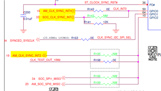
  • Hope there is no issue for INT pin connection from LMK to AM6412.

  • Hi Sreejitha,

    Thanks for the information. The new sequence sound safer because PD# will be pulled high only when the LMK has 3.3V and the AM6412 is ready. I see that there is a capacitor shunted to ground at PD# as Jennifer suggested, this should give extra time for CLK_3V3 to stabilize in case there is some transient ringing behavior that enables the gate early.

    We will take a closer look at the schematic next week.

    Best,

    Evan Su

  • Hi Sreejitha,

    The schematic looks good, we have no further comments. Since you are using a microcontroller you have flexibility to adjust the power-up delays and such if needed in the future.

    Best,

    Evan Su