This thread has been locked.

If you have a related question, please click the "Ask a related question" button in the top right corner. The newly created question will be automatically linked to this question.

LM555: LM555 designed as VCO

Part Number: LM555

Hi,

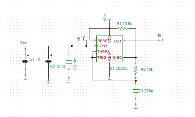
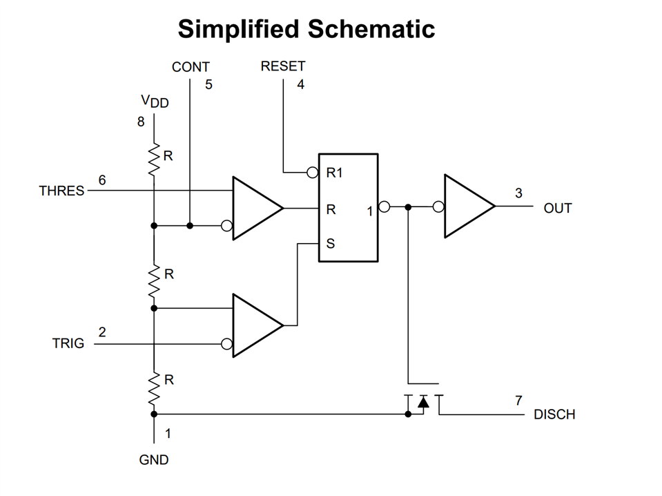
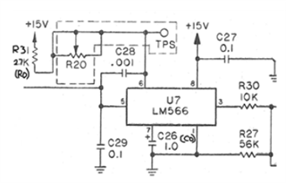
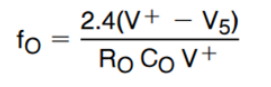
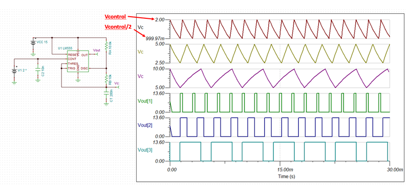
the LM555 timer is designed as VCO with input control voltage to receive certain frequency, but the formula which is given in the datasheet doesn't applicable with this design (there control voltage is grounded).

so, could help us with the frequency out & duty cycle formula if the control voltage pin is provided with input voltage?

  • Hello, 

    If you would like to derive the equations you can use the model below and the simplified schematic of the timer divider shown below as well. You will have to put in your value of control voltage. Alternatively the simulation  would be much easier for analysis. 

    Let me know if I can be of further assistance. 

    Best Regards, 

    Chris Featherstone

  • hi,

    Due to LM566 is obsolete, we want to check is there any possibility to replace LM566 with LM555 timer.

    The VCO is given with control voltage (11.25V to 15V at pin5), Resistor & Capacitor and receive output frequency.

    Example, V5=12.37, V+= 15, Ro= 2700, Co= 1uF  

    By the below mentioned formula (LM566)

    fo= 155.8Hz (output frequency of LM566)

    according to this case (voltage control as input volt), Is LM555 timer output Frequency formula could be derived?

  • Hello Mirthunraju, 

    The LM566 is a dedicated Vco with a typical 50% duty cycle. Using the 555 timers in a Vco application will result in a significant duty cycle change with varying control voltages. 

    The differential equations for a charging cap and discharging cap can certainly be derived as I showed in my last post but it isn't trivial and we do not readily have them available. The internal resistor divider of the timer has three 5kohm resistors internally that form the 2/3 VCC and 1/3 VCC points. When the control voltage is adjusted the control voltage needs to be set as a variable and the differential equations above need to be re-derived. The points become Vcontrol and Vcontrol/2. Please see example below. 


    Running a simulation (attached below) and running 3 voltage levels for the control voltage of 2V, 5V and 10V we can see the associated output duty cycle significantly changes. Note that the capacitor charges and discharges between the levels of Vcontrol and Vcontrol/2. 

    Although the timer can be used in this way it isn't a replacement for a device such as the LM566. Let me know if you have any further questions. 

    555 VCO.TSC

    Best Regards, 

    Chris Featherstone